Free Energy Patents


Nikola Tesla

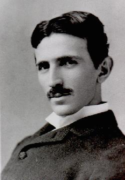
Nikola Tesla 1856-1943

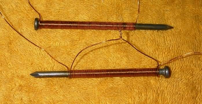
Nikola Tesla - Bifilar Coil for Electromagnets


Tesla - Coil for Electromagnets - 1894

Nikola Tesla Patent 512340

USP 512,340 Page 1

USP 512,340 Page 2 Line 97-105

USP 512,340 Page 3 Line 1-6 Claims 1-2

Two singlelayer coils

Funderburg - Electromagnetic Motor - 1979

Funderburg Patent 4179631

USP 4,179,631 Page 1

USP 4,179,631 Page 2

USP 4,179,631 Page 3

USP 4,179,631 Page 4

USP 4,179,631 Page 5

USP 4,179,631 Page 6

USP 4,179,631 Page 7 Claim 1C

Funderburg - Electromagnetic Motor - 1980

Funderburg Patent 4228373

USP 4,228,373 Page 1

USP 4,228,373 Page 2

USP 4,228,373 Page 3

USP 4,228,373 Page 4

USP 4,228,373 Page 5

USP 4,228,373 Page 6

USP 4,228,373 Page 7

USP 4,228,373 Page 8

USP 4,228,373 Page 9

USP 4,228,373 Page 10 Claim 2


New Measurement on a low voltage winding frequency transformer. Parts are 1 rod of 10 88mm long weldingrods. The spools are 38mm long and 26mm diameter. The spools are filled with 0.75 mm diameter wire. The transformer is made with 1 input coil and 1 output coil.

The input/output voltage has been measured with a 30 Mhz 2-channel oscilloscope and a 1 Mhz frequency generator and the frequency counter using a 2-200 khz multimeter. The input sinewave frequency was 21khz4 and the input current was measured over the 47 ohm input resistor. The output current was measured over the 1 kohm output resistor.

Input Coil Electromagnetic Coil Bifilar Electromagnetic Coil Electromagnetic Coil Bifilar Electromagnetic Coil
Output Coil Electromagnetic Coil Electromagnetic Coil Bifilar Electromagnetic Coil Bifilar Electromagnetic Coil
Input Inductance 1mH825 2mH24 1mH680 1mH99
Output Inductance 1mH642 1mH666 2mH24 2mH24
Input coil voltage 0V6 0V6 0V6 0V6
Input voltage over 47 ohm serial resistor 0V2 0V2 0V2 0V2
Output coil voltage over 1 kohm parallell resistor 0V1 0V1 0V1 0V1


Conclusion: The Bifilar Electromagnetic Coil has the same numbers of turns as the Electromagnetic Coil and does not create more magnetic energy for an overunity transformer than the Electromagnetic Coil. The ampere*turns is the same in an Bifilar Electromagnetic Coil as in the Electromagnetic Coil and creates no additional electric energy. Every patent claiming additional energy from Bifilar Electromagnetic Coil are bogus. However the Bifilar Electromagnetic Coil wire had been wound with deep and not flat as in Nikola Tesla patent. There is a small possibility that Nikola Teslas flat Bifilar Electromagnetic Coil can convert unknown energy to electromagnetic energy after a sparkgap.

- Hermes Atar Trismegistus

NewFrom what I've heard the bifiler back EMF it much higher voltage and can be used to charge a secondary battery. the normalback EMF is never high enough to do that. it creates a spike in the return energy. also some were I read in Rex research long ago that out of gordan Utah a Corp ran test on bifilar pan cake coils and only at resonance did they see a eight fold magnetic increase over a standard pan cake coil.

James

New Hi James

Perhaps "bifilar backemf" (the inductive kickback spikes from a bifilar coil) Is of greater power when first you split then combine the inductive kickback spikes produced. This means bifilar half A is fed the.pulsed DC power (or alternating polarity pulsed DC for AC) And steering diodes capture the kickback spike into cap (s). Then the other half (B) of bifilar is not driven by direct power feed but rather is only induced by bifilar half A. Now either combine kickback spikes from each into common cap or fill up separate caps for each bifilar half. Could be creating a "coherence" condition as Ole speaks about, from W B Smith writings. The capacitors filled need to be disconnected from the coil whenever they discharge to load for real power to be seen with no reflection back to primary input.

Kone

NewHi Kone,

The energy has to be input as two separate parts and then mixed into a coherent single part to be extracted for driving the load. Look at how Pierre Cotnoir did it. His device didn't require resonance which makes it drive different loads without having to readjust everything. He has overcome the tuning bitch. I'll try something like that. But the progress is going very slow. This far two MOSFET hex bridges are completed and working.

Mixing energy is not just mixing voltage or mixing current as both of those parts as well as time (actually change) are parts of energy. Think of energy and not just the parts making up energy. Energy comes in quite many types. It's the output energy that has to be greater than the input energy to be able to extract free energy. The excess free energy is then extracted out of the cosmic background or aether of electrons (or positrons).

Regards
Ole

When air is compressed it becomes hot and the heat can be used to warm drops of water to make steam. The four stroke dieselengine is used to heat air and then water is injected in the combustion chamber.

Steam Engine

Intake: Air is feed from a compressor to the motorchamber.

Compression: Air is compressed to the combustion chamber and becomes hot.

Power: Water is injected into combustion chamber where it turns into steam by the hot air.

Exhause: The steam escapes the motorchamber through a pump.

The compression ratio must be at least 14:1.


NewHermes,

Lots on the page which experiment did you perform?

Noticed the data on water in a diesel engine. One should be trepidatious with this concept as there used to be water injection kits for Diesel engines but they are no longer available as they had a tendency to bend connecting rods and or score main bearings. A gasoline engine can accept water vapor without issue but for some reason diesels can be killed likely due to the expansion from water vapor having more phase change expansion volume than the Diesel oil so likely requires more advance before injection or less compression.

Mick

New ONE SHOULD ALSO BE TREPIDATIOUS (CAREFUL) WHEN installing water injection on a gasoline engine !! I installed water injection on my HOT ROD 500 hp and BENT A ROD !! SO JUST NEED TO BE CAREFUL ON THE AMOUNT THAT IS INJECTED!!

Werner

Cleo L. McClintock patented air motor had a compression ratio of 27:1 and you can see and read his patent here:

Cleo L. McClintock - Air Engine

USP 2,982,261 Page 1

USP 2,982,261 Page 2

USP 2,982,261 Page 3

USP 2,982,261 Page 4

USP 2,982,261 Page 5


New Paramahamsa Tewari - Reduced Reaction Rotary Alternating Current Generator

New Paramahamsa Tewari - Reduced Reaction Rotary Alternating Current Generator USPA 2015/0084467

USPA 2015/0084467 Page 1

USPA 2015/0084467 Page 2

USPA 2015/0084467 Page 3

USPA 2015/0084467 Page 4

USPA 2015/0084467 Page 5

USPA 2015/0084467 Page 6

USPA 2015/0084467 Page 7

USPA 2015/0084467 Page 8

USPA 2015/0084467 Page 9

USPA 2015/0084467 Page 10

USPA 2015/0084467 Page 11

USPA 2015/0084467 Page 12

USPA 2015/0084467 Page 13

USPA 2015/0084467 Page 14

USPA 2015/0084467 Page 15

New Paramahamsa Tewari's Reaction Less Generator


Flynn - Methods for Controlling the Path of Magnetic Flux from a Permanent Magnet and Devices Incorporating the same - 2001

USP 6,246,561 Page 1

USP 6,246,561 Page 2

USP 6,246,561 Page 3

USP 6,246,561 Page 4

USP 6,246,561 Page 5

USP 6,246,561 Page 6

USP 6,246,561 Page 7

USP 6,246,561 Page 8

USP 6,246,561 Page 9

USP 6,246,561 Page 10

USP 6,246,561 Page 11

USP 6,246,561 Page 12

USP 6,246,561 Page 13

USP 6,246,561 Page 14

USP 6,246,561 Page 15

USP 6,246,561 Page 16

USP 6,246,561 Page 17

USP 6,246,561 Page 18

USP 6,246,561 Page 19

USP 6,246,561 Page 20

USP 6,246,561 Page 21

USP 6,246,561 Page 22

USP 6,246,561 Page 23

USP 6,246,561 Page 24

USP 6,246,561 Page 25

USP 6,246,561 Page 26

USP 6,246,561 Page 27

USP 6,246,561 Page 28

USP 6,246,561 Page 29

USP 6,246,561 Page 30

USP 6,246,561 Page 31

USP 6,246,561 Page 32

USP 6,246,561 Page 33

USP 6,246,561 Page 34

USP 6,246,561 Page 35

USP 6,246,561 Page 36

USP 6,246,561 Page 37

USP 6,246,561 Page 38

USP 6,246,561 Page 39

USP 6,246,561 Page 40

USP 6,246,561 Page 41

USP 6,246,561 Page 42

USP 6,246,561 Page 43

USP 6,246,561 Page 44

USP 6,246,561 Page 45

USP 6,246,561 Page 46

USP 6,246,561 Page 47

USP 6,246,561 Page 48

USP 6,246,561 Page 49

USP 6,246,561 Page 50

Flynn - Methods for Controlling the Path of Magnetic Flux from a Permanent Magnet and Devices Incorporating the same - 2002

USP 6,342,746 Page 1

USP 6,342,746 Page 2

USP 6,342,746 Page 3

USP 6,342,746 Page 4

USP 6,342,746 Page 5

USP 6,342,746 Page 6

USP 6,342,746 Page 7

USP 6,342,746 Page 8

USP 6,342,746 Page 9

USP 6,342,746 Page 10

USP 6,342,746 Page 11

USP 6,342,746 Page 12

USP 6,342,746 Page 13

USP 6,342,746 Page 14

USP 6,342,746 Page 15

USP 6,342,746 Page 16

USP 6,342,746 Page 17

USP 6,342,746 Page 18

USP 6,342,746 Page 19

USP 6,342,746 Page 20

USP 6,342,746 Page 21

USP 6,342,746 Page 22

USP 6,342,746 Page 23

USP 6,342,746 Page 24

USP 6,342,746 Page 25

USP 6,342,746 Page 26

USP 6,342,746 Page 27

USP 6,342,746 Page 28

USP 6,342,746 Page 29

USP 6,342,746 Page 30

USP 6,342,746 Page 31

USP 6,342,746 Page 32

USP 6,342,746 Page 33

USP 6,342,746 Page 34

USP 6,342,746 Page 35

USP 6,342,746 Page 36

USP 6,342,746 Page 37

USP 6,342,746 Page 38

USP 6,342,746 Page 39

USP 6,342,746 Page 40

USP 6,342,746 Page 41

USP 6,342,746 Page 42

USP 6,342,746 Page 43

USP 6,342,746 Page 44

USP 6,342,746 Page 45

USP 6,342,746 Page 46

USP 6,342,746 Page 47

USP 6,342,746 Page 48

USP 6,342,746 Page 49


KUNEL, HEINRICH - PROCEDURES AND DEVICES FOR ENERGY PRODUCTION - 1982

KUNEL, HEINRICH - Verfahren und Vorrichtung Energieerzeugung - 1982

Force Perpetuelle Electrostatique - 1937

Perpetual Electrostatic Force (English Translation) - 1937

back to linkpage
suggestion
read and sign my guestbook