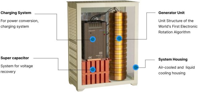
AI Smart Electromagnetic Generators (AISEG) by SEMP

A breakthrough innovation
How AISEG works
SEMP World - Youtube
US20230198368A1
WO2021201518A4
Remanent Magnetism as an Energy Source - Cyril Smith, January 2024
 Experiments Exploring Remanent Magnetism Decay - Cyril Smith, June 2024
Hi Simon,
http://gratisenergi.se/aiseg.htm
Read the world patent application
http://gratisenergi.se/WO2021201518A4.pdf
"As one preferred application of
the generator, there is a system configured to generate various AC power by rotating a
field magnet or an armature using a stored DC power source such as a battery or
another AC power source."
"In addition, the core member is characterized in
that the heat treatment is performed while being composed of pure iron. [37] In
addition, the pole piece is characterized in that the heat treatment is performed
while being composed of pure iron. [38] In addition, in the heat treatment, the core
member or the pole piece is put in a kiln together with the solid fuel, the solid fuel
is burned to heat the core member or the pole piece to a certain temperature or
higher, and the core member or the pole piece is naturally combined with the burned
solid fuel and is carried out by cooling. [39] In addition, the solid fuel is the
white coal. [40] In addition, the core member or the pole piece is characterized in
that the surface treatment with oil is performed."
"In another preferred
embodiment of the present invention, pure iron, more preferably heat-treated pure iron
is employed as the material of the core member 40 and/or the pole piece 80. Pure iron
has high magnetic 28 permeability and excellent electrical conductivity, but has
relatively high coercive force. Since magnetic fields are applied to the core member
40 and the pole pieces 80 alternately or in various ways from the first field magnet
10-1 and the second field magnet 10-2, or the first field magnet 10-1 and the first
and second magnetic fields generated by the second field magnet 10-2 are alternately
applied, it is required for the material to have a fast demagnetization time, that is,
a low coercive force."
"According to the research conducted by the present
inventors, when pure iron is heated to a certain temperature or higher and then cooled
slowly, the demagnetization time is shortened in response to the cooling time. FIG. 8
is a graph showing the demagnetization time characteristics according to the cooling
time of pure iron. As a result of the study, it was confirmed that the demagnetization
time could be shortened to 1/450 second or less if the temperature of pure iron heated
to a certain temperature was gradually cooled for a sufficient time for more than 10
hours. In addition, if the cooling time of pure iron is delayed, an additional effect
of improving magnetic permeability and electrical conductivity is obtained."
"In the present invention, first, the core member 40 and the pole piece 80 are
manufactured using pure iron, and 29 then heat treatment is performed. The heat
treatment is performed using, for example, a solid fuel such as black coal or white
coal, preferably white coal. That is, during the heat treatment, the core member 40
and the pole piece 80 are put in a kiln together with the white coal, and the white
coal is burned to heat the core member 40 and the pole piece 80 to 1000 to 1300
degrees or more."
"And by leaving the core member 40 and the pole piece 80
together at room temperature as it is, the white coal is naturally burned and
extinguished, and then the core member 40 and the pole piece 80 are naturally cooled
together with the white coal do. In this way, the temperature of the core member 40
and the pole piece 80 is gradually lowered in the process of burning and extinguishing
the white coal, and thereafter, the core member 40 and the pole piece 80 are heated to
room temperature by the latent heat of the white coal."
"It takes a
considerable amount of time to cool down. FIG. 9 is a graph showing cooling
characteristic curves according to time of the core member 40 and the pole piece 80
that are heat-treated through the above-described method. And, after the heat
treatment is finished, impurities such as white charcoal are removed from the core
member 40 and the pole piece 40, and finally, rust prevention treatment is performed
with oil or the like."
It seems that metallurgy and materials engineering is
the secret of this invention.
But I don't understand how there is a electricity
gain? In ferrite rods, if you charge a inductor with electricty and disconnect it.
There is always a back electro magnetic force like in John Bedini's patents:
http://gratisenergi.se/bedini.htm
But this back emf is always less than the charge of the inductor.
Best Wishes, Hermes
Hi Hermes,
See
https://www.lenr-forum.com/forum/thread/7086-semp-electronmagnetic-generator/
to get an idea of what they are doing here. Clues near the end of that string.
It'll run as long as the batteries last, I think. Note the use of light-bulbs
as the load, and also that they measure the RMS volts and RMS amps and multiply them
together to determine the power delivered. They aren't measuring phase difference
between the AC volts and amps, so they are measuring apparent power, not real power.
This way of trying to get overunity has never worked, though many people have
been fooled by it....
Best regards, and Merry Christmas,
Simon
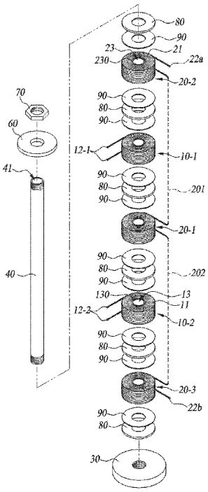
Non-rotating alternating current generating device

I have experimented with 5 coils of the type DR-2109 E and 1 ferrite
rod. I measured input and output voltage with the oscilloscope Voltcraft 632FG. It has
a 0-1 Mhz built-in frequency generator. I used the frequency 6 kHz and the load
12volt/50milliampere bulb on the output voltage of the transformer.
The
strongest glow from the bulb was when I used the coils as in the patent. From top to
bottom Secondary-Primary-Secondary-Primary-Secondary 12 volts in and 9 volts out. I
tried Primary-Secondary-Secondary-Secondary-Primary and then the glow was not as
strong from the bulb 10 volts in and 7 volts out.
I also tried 3 primary coils
and 2 secondary coils. Then the glow from the light bulb was greater with reverse
construction from the Primary-Secondary-Primary-Secondary-Primary pattern. 14 volts in
and 8 volts out. I also tried Primary-Primary-Secondary-Secondary-Primary. But then
the output voltage was only 6 volts with an input voltage of 11 volts. The light from
the light bulb was then the lowest.
My conclusion is that SEMP has experimented
with different coil configurations and the best one is according to the patent. But
they probably have at least one more secret that makes the transformer have a claimed
efficiency of 1600%
Hermes
I have done two more experiments
after the patent writing.
I measured the inductance on the output to 3mH83 and
the inductance on the input to 2mH80. I used two 330nF capacitors.
One on each
output wire from the output in series resonance and found that the output voltage was
10 volts with the input voltage being 14 volts.
I then connected a 220 nF
capacitor in parallel with the input and then the input voltage decreased to 13 volts
and the output voltage was as before 10 volts. The frequency was 8 kHz.
The
conclusion is that SEMP must have at least one more secret because the measured
efficiency was 1600%. It is very likely that SEMP uses
Remanent Magnetism as an Energy Source as Cyril Smith
writes in his thesis.
Hermes
On december 26 I wrote the following E-mail to SEMP, but
still no response:
I am responsible for the world's largest free energy link
page:
http://gratisenergi.se/free.htm
I have made my own page for SEMP at:
http://gratisenergi.se/aiseg.htm
and I will post my questions and your answers on that page. Here are my
questions:
1) I saw that you used lamps as a load for your AISEG at COP28 and
measured the voltage with a voltmeter and the current with an ammeter. That's good,
because the phase shift between voltage and current in a resistive load is zero. But
have you tried loading AISEG with a car engine and measuring the output power from
AISEG with a wattmeter?
2) What is the cost of an AISEG with the output power
100KW to drive a 100 KW car electric motor?
3) Have you already figured out
that when the car is not in use, AISEG can be used to supply electricity to the grid?
4) Is the cost greater with AISEG to deliver AC voltage than DC?
5)
Does AISEG use a battery for input power and does AISEG charge a battery for output
power?
6) I think you should check out my site Benitez-Brandt-Bedini
http://gratisenergi.se/benitez.htm
and try using a transformer with spark gap. Just as anonymous describes for
Benitez's patent:
https://potentialtec.com/121561.pdf
http://gratisenergi.se/sparkgap.htm
Best Wishes, Hermes
back to linkpage
suggestion
read and sign my guestbook


