Don Smith books and videos
Don Smith books:
Don Smith - An Answer to America's Energy Deficit 73 pages - 7,327 kB
Don Smith - Resonance Energy Methods 105 pages - 2,000 kB
Don Smith - Resonance Energy Methods 119 pages - 42,153 kB
Don Smith - Resonance Energy Interview - 779 kB
Compilation of info Don Smith shared on FreeEnergy Yahoo group
We Are Infinite Energy
Radiant Energy Induction Using RF Pulsed Plasma - 4,684 kB
Nikola Tesla DC impulse energy technology - 12,397 kB
The Resonance Energy Device Explained - 1,06 MB
Mosfet Switch Board
 Understanding The Don Smith Capacitor Energy Method By Joel Lagace:
4.75 KW Energy Generator Don Smith Generator by Joel Lagace
Don Smith videos:
Donald L. Smith - Inventors Weekend 2001
Donald L. Smith - Resonance Energy Methods
Don Smith - Resonance Energy Methods
Donald L Smith Device bonus part 1
Donald L Smith Device bonus part 2
The Don Smith Device RUS-(part 1)
The Don Smith Device RUS-(part 2)
Donald L Smith Device Russian Video
I look forward to repeatable instructions! Can I put the full instructions on my Don
Smith page?
http://gratisenergi.se/donsmith.htm
Maybe you should consider sell it as a Kit? I don't know the price but Andrea
Rossi wants $25USD for 10 watt and $250USD for 100 watt. Is it possible to loop it?
Andrea Rossi's E-Cat SkLep is selfrunning with no input power.
Can your Don
Smith version 2 and 3 use a battery as a starter?
Best Wishes, Hermes
jukka.kortela(at)artificialintelligence.fi believes he have discover the secrets of
Don Smith energy inventions and he is willing to give the instructions of how to build
them to the world for free by sending request to his e-mail. The following is his
message:
I will send the detailed instructions the people that want to build
the device through the email. My plan is to give the instructions for free. If anybody
need more help I can instruct through email.
My profession is University
Lecturer and I have real degree, Doctor in Technology in Chemical Engineering. And my
exact field is Process Systems Engineering, I teach control and automation, signal
analysis and physics and chemistry based dynamic modelling full time.
Why I
give it free is that I am already doing bigger things. I also do audio software that
improves sound quality for macOS, Windows, Android and iOS. It is named BAPU bapu.fi.
In addition, this has been hidden too long time, over 100 years. Best regards, Jukka
Dear Jukka, I have updated my Don Smith page with your contact information and wishes.
Wait until the the end of your work day for my Don Smith page to update:
http://gratisenergi.se/donsmith.htm
I have two questions. 1) Do you have instructions of how to wind the coils?
instead of buying them? and 2) What are the total part cost for a 100 watt Don Smith
Unit?
Best Wishes, Hermes
I have a good method how to wind The big coil in Don Smith Device 3.
I have
also Solidworkz and STL file for 3D printing of the frame supports for coil. Small
coils are super cheap ($11) I would not do those myself. The free energy parts are max
100 euros.
Super capacitors are two times 70 euros. Kemet 12 V 5F. 400V->12V
transformers are super quality. 250 euros and I use one for the signal generator and
one for output.
Hi Simon,
Is there any broken symmetry in the
Don Smith devices?
http://gratisenergi.se/donsmith.htm
and even if you can get 100 watts out for 0.3 watts in. There is also the
power of the wallet to consider?
100 watts of the Don Smith device cost 500
euros. While Andrea Rossi E-Cat SKLep cost 250 US Dollar for 100 watts. Here is the
link to the description of E-Cat SKLep. As you can see Andrea Rossi has left the cold
fusion field and now into high voltage devices:
https://e-catworld.com/2023/01/06/rossi-patent-application-electric-energy-generator-and-electric-energy-generation-method/
Best Wishes, Hermes
Hi Hermes,
I can't see any broken
symmetry. Looks to me that he's measuring VARs and just multiplying the amps (from an
ammeter) by the volts (from a voltmeter) without looking at the phase difference. At
resonance, the phase difference between volts and amps is almost 90�, giving very
little real power.
Get a system with a high Q, and feed it a resonant
frequency, and you get a much higher voltage and current in the circuit than you're
feeding in. Using a Quartz crystal, that can be 10,000 times the input volts/current
(normally we'll fix it so the voltage doesn't go high, but the current does, since
otherwise it gets hard to find semiconductors to drive it, however see the
piezo-ceramic HV generators that multiply the voltage instead).
If Don Smith's
devices actually produced more energy out than in, *someone* would be making them and
selling them, maybe especially the Chinese. Also see the number of people who tried
this at overunity.com. Thus it isn't OU. It doesn't work.
I'd suggest you
forget Andrea Rossi. His stuff has been a wash from the start, though at one point he
might have been honestly thinking he'd got a result through being unable to measure
things correctly. By now, I doubt if he believes he's got anything real, but he likes
the income it gives him. Maybe also likes the idea of fooling a lot of people too....
I read some of the Don Smith document, and he states that the number of
radio-sets picking up the transmitted wave doesn't affect the power needed for the
transmitter. Of course that's wrong - if you put up an antenna and take power out of
the radio wave, then the antenna will transmit a wave in antiphase to the transmitter
and reduce the wave energy at that point - you get a "shadow" from the antenna. Thus
one of the propositions he relies on is basically wrong, and the wrongness of the rest
follows.
There may be ways to break the normal symmetries by exploiting the
finite speed of light, and thus that the wave arrives with a time delay and the
reaction force returning also has a time-delay. It would nee pretty high frequencies
to get the 1/4-wave length down to a reasonable size, and I think no-one has yet
tested this by experiment with a combination of a high-enough frequency and the right
lengths of wave. The idea here is that by the time the wave from the generator reaches
the coil, passing through a ferrite rod, it's 1/4-wave delayed, so the reflected wave
going back (through Lenz's law) reaches the generator 1/2-wave delayed and thus
accelerates the generator rather than decelerates it. I think the speed of a wave in
ferrite is relatively slow, so this might be possible to implement in a system that
isn't too large and where the central magnet doesn't break through spinning too fast.
I've just looked up the permittivity of ferrite, and that varies with
frequency, meaning that the speed of light in ferrite also varies with frequency
(dispersion will be large) so that would need to be allowed for in the design. Still,
might work....Problems are of course the losses in the ferrite at high frequencies,
and you'd need to measure the delay between the magnetic wave going in at one end of
the ferrite and the reaction reflecting from the other end of it. So a fair amount of
legwork needed before you could design something with a chance of working. The rotor
of a disk-drive (or DVD) motor might be a place to start, being a magnetised ring with
a N pole and S pole across the diameter, and obviously designed to run at 10krpm or
above.
Then a star of ferrite rods with pickup coils at the far ends, with an
outer ring of ferrite to connect the outer ends of the ferrite rods and complete the
magnetic circuit. Get the core spinning at the right speed, and you should see the
outer ring magnetising with a 90� phase shift and the power needed to drive the
spinning ring at the centre go down because it's seeing an attractive force rather
than a drag, because of the delayed wave. Might be strong enough effect to not need
pushing once it reaches the right speed, and thus self-run.
Since Lenz's law is
the basic symmetry that ensures that energy in electromagnetic systems is conserved,
there are currently only two ways I know to break that symmetry. One is the
normal-conductor to superconductor transition, giving rise to the Meissner effect
where magnetic flux lines are expelled, and where the transition can be affected by a
laser of the right photon energy. The other is to exploit the delay from light-speed
as I've just explained. There might be a third from exploiting the change in
permeability of a ferrite under mechanical stress, and thus maybe being able to change
the route of magnetic flux through a system using less energy than you can gain from
the change of flux, but I haven't fully explored that.
Still, it's a pretty
fair bet that the almost all "historical" claims (as documented by Pat Kelly) didn't
actually work, since enough other people have tried them by now that, if one actually
worked, we'd have been using it commercially for a while and you could buy one
off-the-shelf today. What those files tell you is what not to do to succeed - to have
a chance of succeeding you need to do *something else*. Exceptions are the Lovell
Monotherm (which works as claimed), the Papp Noble Gas Engine (though currently no-one
knows exactly why that worked, except that it's fission-powered and not fusion as
claimed), and some environmental energy collectors (maybe Testatika machine, certainly
spiky balloons and line electrets in air).
Otherwise, use your head to see if
it worked or not. If it worked, then someone would have commercialised it because
there's a lot of profit to be made. If it's cheaper than digging up oil or coal or
gas, then the energy companies would have invested in that instead.
Best
regards, Simon
In addition to device 2, I am same time building Don
Smith device 3. I have understood that it uses Barker & Williamson coil 3064
Inductance: 32.0 microHenrys, coil length: 10 coil diameter: 3 turns per inch: 4, wire
size: 12 AWG.
Rick Friedrich said that it might be different size: What really
matters is to understand fully all the concepts.
I have myself calculated it
according to the information provided:
height_of_coil = 7.62 cm
length_of_coil = 25.4 cm
distance_between_wires = 0.635 cm
wire_length_one_turn
= 23.9474 cm
lenght_of_the_whole_wire = 957.8943 cm
Equation:
wire_length_one_turn = sqrt(distance_between_wires^2 + (height_of_coil*pi)^2)
lenght_of_the_whole_wire = 40 * wire_length_one_turn
I made the coils myself
because there wasn�t available this coil when I started
"Main coil" (coil L2)
capacitance = 0.000000047 Farads = 0.047 microFarads
inductance = 0.0000126 Henrys = 12.6 microHenrys
resonance = 1/(2*3.1415926*sqrt( 0.0000126*0.000000047 ))
resonance = 206.8168 kHz
206.8168 kHz x 144 = 29.781 Mhz (related to wavelength, speed of light in
copper) 206.8168 kHz Devided by 6 (3, 6 and 144 numbers work great)
operating
frequency: 34.469 kHz
If you do it without red wire, the frequency 12.400 kHz is
better: To have standing wave.
standing wave: 3 (1 and half), 6 (double), 9 (0)
1, 4, and 7 are compressing harmonies (positive), or (4 7 10 is the same thing) 10
reduces to 1 2, 5, and 8 are expanding harmonies (negative))
Fibonacci: 1 2 3 5
8 13 21 34 55 89 144
144 can be devided with 3, 6 and 9. This also important.
Good information:
https://www.electronics-tutorials.ws/accircuits/harmonics.html
I have unwinded the coil on the center the and connected from the center. That is the
reason for the inductance about 12.6 microHenrys
pecado
For the device 2, I use coils that has wire length about 990.68 cm and inductance of
150.95 microHenrys. They are from:
https://www.r-charge.net/Extra-Induction-Coil-without-base_p_338.html
I use
frequency:
capacitance = 0.000000000180 Farads = 180 pF
inductance = 0.000150
Henrys = 150 microHenrys
resonance2 = 1/(2*3.1415926*sqrt( 0.000150*0.000000000180 )) 968.5861 kHz
Got it work in: around 930 kHz
I use same frequency from start to end. It is
the easiest way. Other way is to use harmonies, partials, differential tones.
However, the receiving coils can be pure chords (in musical terms) of the center
The best book about the differential tones and harmonics is
On the Sensations of Tone, Hermann Helmholtz from 1800's
pecado
The following links have helped me do the right calculations. I count
everything and then combine. This makes working much easier and it is much safer. It
is important that the frequency has an accuracy of about 3 significant digits. You get
much better efficiency. Therefore, the wire length must be exactly the designed length
and you can measure several capacitors and choose the ones with the right value:
Series resonance:
https://www.electronics-tutorials.ws/accircuits/series-resonance.html
Parallel resonance:
https://www.electronics-tutorials.ws/accircuits/parallel-resonance.html
pecado
Honestly, I have got best hints from
https://www.r-charge.net/Renaissance-Resonance-Induction-Coupler-Kit-_p_305.html
and
https://www.r-charge.net/resonance-induction-coupler-kit-part-2.html.
This book explains the best the electric fields and some fundamentals of free energy
in really good way. There is one small error (Nikola Tesla 's equation): Research in
Solid State Free energy generators (latest version - working here).docx. I call it 723
pages book
The rest I have figured by myself just by reading a lot different
literature.
pecado
To get "Don Smith device 3" fully
working, it is much easier to test first with smaller device (also that you don't hurt
yourself) with the bifilar coil (L2 with CW and CCW rotation winding matching single
coil in Resonance Induction kit 1) included in:
https://www.r-charge.net/resonance-induction-coupler-kit-part-2.html.
Quote from the link:
"This is the next addition to the Resonance Induction
Coupler Kit (R.I.C.K.) that adds more parts downstream to make a testing bed to more
safely learn how to make Don Smith magnetic resonance energy systems, specifically
Earth Electrical System II."
I have got lot of good information from this kit
and I have got also 1/4 wave with red wire working. It has a lot of parts and the
value of the information and parts is much than $250. And this bifilar coil can be 100
% sure excited with much lower frequencies by utilizing harmonics or differential
tones.
pecado
For small Don Smith Device 2:
I am
using this for accurately measuring amperage
Tekbox tbcp1 RF current probe
Max. primary current (DC � 400 Hz): 80 A
Max. primary current (RF): 3 A
10 kHz - 250 Mhz
(The amperate is calculated from the voltage measurement according
to the chart in the manual)
You can it, for example, from here:
https://iosignal.fi/?s=rf&submit=Search
Now there is new models that accept thicker wire with thick plugs and the
frequency range goes from 1kHz to 800 Mhz. This is the absolute the greatest way to
measure RF amperage.
I am using this for accurately measuring voltage 0 - 20000
V:
Testec TT HVP 15HF
pecado
I had to study a lot of
physics and then I finally got it how to get an amperage. I also studied a lot of
music theory. I get 350mA from the coil already connected in series and at the same
time 400V. Then the 6 wireless coils around the center coil repeat 70mA and same time
about 200 - 300 V each one. The solution was right thinking and then the really simple
connections to the ground.
I'm not here to advertise and I have no business
relationship with the following, but the name says a lot in r-charge.net front page:
"Also the Resonance Induction Coupler Kit Part II for learning how to
complete a Don Smith System." It has been there from the last year 2022.
There are a lot of good hints that finally make you get it if study all the links
included and some additional literature, for example, On Sensations of Tone,
Hermann von Helmholtz and The Universal One, Russell, Walter to get rid off
of the ordinary thinking.
pecado
If the center is 960 kHz
= 0.96 Mhz, some of the coils around the central coil can use 100 pF capacitor. It is
1.28 MHz.
In music, chords MI and FA, for example, C-E, C-F you can use 1.333
(4/3) and 1.25 (5/4) ratio and they don�t disturb the center. It is funny, that you
find capacitors in those exact positions. I have playing violin 39 years and done all
music theory (I have a diploma for it), so I know what I am talking about. It is not
any new age stuff in a negative sence.
Both ascending and descending
harmonies (positive + and negative -)
ascend MI(2) SO(5) = negative harmonies
(expanding)
descend LA(7) FA(4) = positive harmonies (compressing)
This is
how you have to design it.
pecado
Hi
I would
remove Simon 's text in:
http://gratisenergi.se/donsmith.htm
All what he is saying absolutely wrong
and what you are doing is spreading same misinformation as everybody else. Almost
everybody nowadays because they don't know how the universe works. The systems are
open systems and not closed systems as almost everybody thinks.
Best regards,
Jukka
Hi Simon,
Jukka claim 6 watts in for 2500 watts out, but I
don't know if its VAR he is measuring?
We can make the following deal. When I
have read the documents. I will notify you, so you also can request them from Jukka.
My goal with reading the documents is to see if one can build a low voltage device
with the output in resonance that can have a big load.
I don't like high
voltage, because it is dangerous. As I understand the device is high frequency, so you
need a FET as a driver. Jukka has learned that is better to use squarewave without a
high voltage transformer as in the original device.
Best Wishes, Hermes
and you don't need to reply to this e-mail.
P.S Jukka claim 20 Volt*300mA as
input and more than 250 Volt*10 Ampere as output.
Hi Hermes,
Almost certainly VARs, so pay attention to whether he's measuring the voltage and
current using separate meters, and not looking at the phase. You can also put an
electric kettle on the output and boil some water. Temperature at start can be
measured, as can quantity, so how much energy it takes to boil can be calculated. How
long it takes tells you the power.
Boiling some water, or heating it through a
temperature range, is a good way to sense-check these sorts of things.
Many people have tried using a resonant circuit to attempt to get more power out than
in. It's always failed. Mentioning the resonant circuit implies they're measuring VARs
and it's not real power.
Resonance is an energy store. You can get high
voltages and current, but the energy input feed here is 6W so that's all you can pull
out of it (minus losses) on a long-term basis.
As I've said before, you need to
try a bit harder to really get OU. You also need to figure out how to break
symmetries, which most of the time will involve quantum mechanics and being somewhat
sneaky.
Best regards, Simon
Hi Simon and Jukka,
http://gratisenergi.se/donsmith.htm
What do you think about Joel Lagace
article?
http://gratisenergi.se/don_smith_capacitor.pdf
and the overunity video. Is
he measuring VAR?
https://www.youtube.com/watch?v=lzHaGBQZ4P4
Best Wishes, Hermes
P.S
I got a COVID-19 infection last tuesday and I still haven't recovery totally.
I got high fever and difficult to breath. So I thought I might call an ambulance.
But then I remember the I had two prayer clothes from Svein-Magne Pedersen:
http://gratisenergi.se/healing.htm
so I used them and fell asleep in and
half hour. Next morning I had almost no fever
but I am weak until today. They
say that the critical days are day 5-7. If you get more sick.
Your in trouble.
I will call the ambulance if I experience difficult to breath.
http://gratisenergi.se/corona.htm
Hi Hermes,
As usual, if someone is making money from telling you how to make
Free Energy, rather than making and selling either the machines or the energy, it's
pretty certain it's a fraud. That's just life - if their machine really works it's
worth a fortune, so why are they trying to make some money selling the plans or trying
to earn money for lecturing about it?
Prove it to pretty-well any businessman
and you've got a sponsor to make and sell the machines for a share of the profits.
Trouble is, you do need to prove it. See the Earth Engine and Dennis Danzik, where
he's fooled many people for years but is getting to the point where his backing won't
last that much longer without installing actual working machines, which of course he
can't do. So yep, for a while you can get sponsor even if you can't prove it right
now.
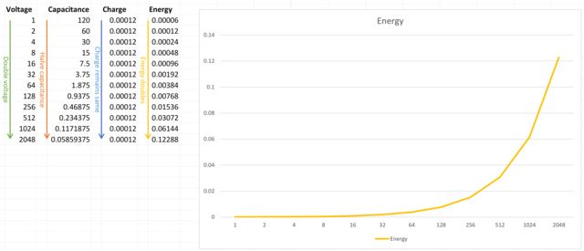
Page 6 of the .pdf, the energy calculation for the capacitor is wrong,
with that 10 microfarad cap at 10 volts having half a millijoule (0.0005 J), not 5 mJ.
Later on, page 9, comes the idea of flipping one capacitor of the two charged ones to
get back the "lost" energy. Actually, both caps would be discharged, and you end up
with some current flowing but you don't get the energy back and both caps end at 0V
across them. Again, the stored energy is a factor of 10 out anyway. Not sure I want to
go through the other 40 pages and detail the problems, but again I'll state that he
hasn't got a working free energy system since if he did it would be very obvious (and
he'd be stinking rich).
Note that when you put two equal charged capacitors in
series to get more voltage, that doubles the voltage and halves the capacitance, so
it looks like you could use switches to charge capacitors in parallel and discharge
them in series to double your input energy. Energy = 0.5CV�, after all.
I'd suggest you try this in LTspice using the inbuilt Switch function
rather than using real MOSFETs since that way you lose the difficulties associated
with connecting real FETs. Tell me how you get on. Note that LTspice doesn't run
checks for conservation of energy, just runs the simulations of the components, but
will still conserve energy if that's what would happen in real life (but within an
error margin). Double the energy out is way outside the error margin, so if you see
that it's either real or you've messed up somewhere. Yep, I tried this a long time ago
.... Still, you need to run the simulation and see for yourself.
Some other
notes: you can transfer the energy in capacitor A to capacitor B, and meantime change
the voltage, by first discharging cap A to ground through an inductor, then when it
reaches 0 volts switch the ground side of the inductor to cap B and the cap A side to
ground, and then disconnecting the inductor when the current reaches zero. Again, you
can simulate that in LTspice, using the "switch" components to save having to set up
drivers for real FETs, and get some idea of how these things really work and how you
can convert your initial energy to whatever voltage you want. Real components of
course have losses, so there are limits to how far you can push this in real life as
regards voltage translation and still be pretty efficient, but once you've got that
sussed you'll be less likely to be taken in by claims you can gain energy this way.
Note here that if you discharge to ground through a resistor the current decays and in
theory never reaches zero and you thus never get all the energy out of the capacitor.
Using a coil instead and getting the switches in the right places enables you to get
all the energy out of the capacitor. Means that you also need to get the timing right
as to when to switch, and real components are not precise values, so for real life
you'd need sensing voltage/current and a microcontroller. Hence get the idea using
simulation and switches that are easy to control and can be connected in any order.
Note that if you put in a transformer in the circuit rather than a simple
inductor, the inductance drops if you take power from the secondary and so it passes
less energy on to the second capacitor. Again, no energy gain, just you have control
over how much or little you lose.
I know I keep stressing this, but look at the
symmetry here - you aren't breaking any symmetry associated with conserving energy, so
it will conserve energy.
OK, reached page 18 and he's wrong that the secondary
doesn't "feel" the secondary current because the primary current is displacement
current. If current flows through the secondary, the primary will feel it. Further on,
skimming, he's still getting the capacitor energy wrong. 0.5 x 10 x 1e-6 x 10 x 10
equals 5 x 1e-4 or 0.5mJ . Worked it out by hand here to cross-check the calculator.
OK, giving up on that. It's just too much wrong, and almost by definition it
doesn't actually work.
Best regards, Simon
Hi Hermes,
Forgot the Covid problem. Good idea to get Ivermectin if you can
("horse-paste" de-wormer if that's what you can get) and if you can't get that get an
antihistamine. If you end up with a cytokine storm (result of your immune system
kicking in and stopping the virus) the antihistamine will stop that doing damage.
If you've had the vaccine and boosters you likely won't get too ill. However,
high fever and difficult to breathe isn't a good sign, and better call the ambulance
earlier rather than too late. The antihistamine would however help with breathing. Not
the right time of year to find that in the shops, but a pharmacy should have it.
Read
https://www.ncbi.nlm.nih.gov/pmc/articles/PMC7833340/#!po=34.9057 for how an old
folks' home in Toledo cured their patients. Tells you how you can fix yourself.
Best regards, Simon
Hi Simon,
thanks for your antihistamine idea! I bought it yesterday and took
one pill yesterday. It was a godsend I stop vibrating and felt fine.
It worked
for almost 24 hour. Then I had much less symtoms so I took another today. I have no
fever and are awake longer not feeling tired.
With this antihistamine speed. I
will be OK without antihistamine pills in a few days. I will be back to normal.
Again, many thanks,
Best Wishes, Hermes.
P.S I got the COVID-19
on tuesday 21 january. Now I am on 9 th day and having no fever since a few days. I
have won this third battle in my life against COVID-19. Each of them has been special.
Not having exactly the same symtoms.
Hi Hermes,
Glad you were able to find the antihistamine at this time of year.
As medicines go, the antihistamine is low-risk (no nasty side-effects, main
one is a bit of drowsiness so best not to drive or run dangerous machinery), so if it
didn't work for you it wouldn't cause any harm either.
Same low-risk attribute
on the Ivermectin if you can find it available. In fact it's safer than Aspirin.
Both probably help with a normal non-Covid 'flu, too. Not much data on that
yet, but going on how they work and what's happening that ought to be true. Thus
something to try (because it's low-risk) if you get 'flu.
I wish I'd known that
earlier than I did....
Best regards, Simon
back to linkpage
suggestion
read and sign my guestbook