LC Resonance for Free Energy
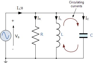
Parallel Resonance Circuit
Simple Parallel (Tank Circuit) Resonance
Parallel Resonance
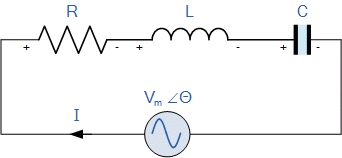
Series Resonance Circuit
Simple Series Resonance
Series Resonance
Unlimited Free Energy, Overunity With Solid State LC Resonant Circuit
First thing first, make a couple backup copies of this information, just in
case it is censored and removed from the public.
The information below are
being explained and released into the public domain, hopefully for the betterment of
mankind. If you can, please do help to make this information a well known public
knowledge. Ignore those who tries to claim to be the original author of this now
public domain information, or rewording of this info. Ignore their claims to fame or
whatever their motives...
In bits and pieces, all information below are already
in the public domain. Basic principles and usage profile for each component are well
explained in electrical circuit text books. The trick is to put them together in
certain combination and applying basic circuit analysis, like pieces of a big puzzle.
WARNING !!! "Electrical circuits Can Be Very Dangerous, even
Deadly!!!" The electrical circuit setup below are operating with AC Voltage.
Experiment at your own risks.
Unlimited Free Energy,
Overunity In Electrical Systems
The key to "Overunity", or
"Free Energy" is to identify all possible components and subsystems that can be used
to extract energy from (an electrical circuit, in this case.) Then reduce or
eliminate inefficiencies for each of those components and subsystems. If possible
substituting other components or subsystems that are more efficient. When the cost of
running a component or subsystem is reduced to virtually zero, any energy output from
it is practically free.
With text book theory, the LC Resonant circuit is using
AC sine wave signal. Of course, experimenters can try with other AC wave forms, DC
wave forms, DC pulse signal… Some of these wave forms and pulse signals may not be
measured properly by regular multimeter, so perhaps oscilloscopes with fine enough
scanning resolutions can pickup such signals, beware that some circuit conditions may
damage an oscilloscope and/or its components.
Any component or subsystem that
uses virtually zero Watts (zero power), and can give any power output, is a component,
or subsystem that obviously does produce Free Energy, Overunity power output. So
considering some components or subsystems that uses virtually zero Watts, zero power
in theory (or very low Watts in practice), and some way(s) to extract energy…
A) Series-LC circuit is a case of Series-RLC circuit, where R is zero Ohms. In
theory, with AC sine wave, Series-LC circuit at Resonant frequency becomes "Short
Circuit", it behaves like a straight wire with zero impedance, zero resistivity (zero
Ohms, consuming zero Watts), current flows freely through it. So voltage across
Series-LC circuit at Resonant frequency is theoretically zero Volts. When tuning the
subsystem for Resonant state, adjust so that the voltage across Series-LC subsystem is
zero or as close to zero as possible, or current flow is as high as possible. Any wire
carrying AC signal can be cut and inserting a Series-LC Resonant circuit, if its
Resonant frequency matches the AC signal frequency, it would use up virtually no
power, zero Watts in theory.
B) Parallel-LC circuit is a case of
Parallel-RLC circuit, where R is infinite. In theory, with AC sine wave, Parallel-LC
circuit at Resonant frequency becomes "Open Circuit", no current flow, uses zero
Amperes, yet "electrons are actively flowing back and forth" between inductor L, and
capacitor C. The subsystem still needs AC input at the Resonance frequency
continuously applied to maintain the Resonant state, even though zero current (zero
Amperes, consuming zero Watts) flows in/out of the Parallel-LC subsystem. When tuning
the Parallel-LC subsystem for Resonant state, the current flow in/out should be zero
Amperes, or as close to zero as possible, as-if the Parallel-LC subsystem is not
there. So any two wire branches which have AC voltage signal, adding Parallel-L
circuit with Resonant frequency matching the AC voltage frequency would act like "Open
circuit", which is infinite impedance, infinite resistivity, zero current, zero
Amperes, consuming zero Watts in theory.
C) To extract extra energy from
an electrical system, replace an inductor coil L with a transformer’s primary coil.
Electron flow in the transformer primary coil will stir up the magnetic flux and
induce current in transformer secondary coil. The more electron flow and the faster
the frequency, the more magnetic flux is stirred up, inducing more electron flow in
transformer secondary coil. This is virtually "Free Energy", or "Overunity", since
Parallel-LC Resonant subsystem, or Series-RC Resonant subsystem use zero Watts, zero
power at Resonant frequency in theory, or very low Watts in practice. Any amount of
Watts output divided by zero (or very low) Watts input, result in the COP (Coefficient
Of Power) for the LC Resonant subsystem. Of course, the higher the transformer
efficiency, the better the COP for the LC Resonant subsystem.
D) Free
Energy with spark gap. Same amount of current flow on each side of spark gap. Each
side of spark gap can have one (or many) Series-LC Resonant subsystem(s), each has
zero impedance and uses virtually zero Watts. Both sides of a spark gap can be the
ends of one (or many) Parallel-LC Resonant subsystem(s), each has infinite impedance
and uses virtually zero Watts.
E) Generate unlimited amount of Free
Energy. In theory, at LC Resonant state, it costs zero Watts and should not interfere
with the rest of the system, there is no limits as to how many LC Resonant subsystems
can be added in the whole system. Multiple Series-LC Resonant subsystems can be added
in series. Multiple Parallel-LC Resonant subsystems can be added in parallel with each
other. Some people may say that multiple Series-LC Resonant subsystems in series just
divide the voltage among these Series-C Resonant subsystems, thus lowering the voltage
of each system. It is not the case with Series-LC Resonant subsystems. Remind those
people that each of these are "Short Circuit", have zero impedance, zero resistivity
(zero Ohms,) and voltage across each subsystem is virtually zero Volts, while the
"full AC current" of the circuit branch is flowing in the transformer primary coil of
each of these Series-LC Resonant subsystems. Note that AC current is flowing back and
forth in the transformer, so 60Hz AC in transformer is equivalent to 120Hz PWM (pulse
width modulated) DC in term of magnetic flux stirring, or magnetic movements, or power
generation, power transfer by the transformer. The faster the magnetic movement, the
more power generated. So for same voltage, same current, in the case of LC Resonant
subsystem power extraction, Terra-Hertz are better than Giga-Hertz, better than
Mega-Hertz, better than Kilo-Hertz, better than Hertz in LC-Resonant subsystem power
generation or extraction. Be sure to check the transformer core (or air core) is
working efficiently for a particular frequency range, by checking the power output of
the transformer secondary coil, not losing too much power as heat in the core, or the
wires.
F) Also, consider perhaps, having Series-LC Resonant circuit
where one capacitor C and multiple inductor coils [L1, L2... Ln] connected in series
as equivalent to one inductor coil, so need to re-tune for Resonant frequency, or
Resonant state. Since the full current of the circuit branch is flowing in each
inductor coil, replacing each with a transformer, will now yield multiple output with
one capacitor, possibly reducing system components cost.
Output to bridge
rectifier, then buffer, or filter, using simple capacitor C, or CLC in Pi
configuration, or LLC, or LCLC… Or, look up various good-old (20 years or older to
avoid any potential 17-yr Patent protection) AC to DC, or DC-DC power supply designs
for smoothing DC output. Even for DC filtering sub system, experimenters may want to
try using transformer instead of inductor to see if additional power can be extracted,
books do not say much about DC voltage and transformers, however DC voltage will
affect transformer output. Quick example of that is a simple Joule Thief circuit, even
with DC power, a simple air core coil with a few turns of two-wires, it does give
output in the secondary coil. Perhaps air core transformer will cut down on heat in DC
voltage (power) transformers. Again, any energy can be extracted with a transformer in
place of an inductor is literally free. In theory it may affect the phasing angle of
the input and output signal, but for energy extraction, DC buffer and filter will make
it smooth DC ouput anyway.
For a small system, it may be much harder to get
Overunity, especially using just one transformer, because overhead cost of running the
system may be proportionally higher. Transformer efficiency is also very important.
The following simple examples are assuming transformer with only 60% efficiency, 10W
in primary coil only produces 6W in secondary coil.
For example, let’s say the
system main power source uses 15W of power to generate some 10W of power as AC signal,
the main circuit loop send this 10W of power to a workload. Adding a single Series-LC
Resonant subsystem, that is 10W of power in the transformer primary coil, assume a
transformer efficiency of 60 percent, then 6W of power is extracted from the Series-LC
subsystem. So the input power is 10W, and output power is 10W + 6W = 16W, perhaps
less after conversion to DC, filtering... The system is within the COP 1.0 to COP 1.06
range, which could still be argued as measurement error, or equipment inaccuracy, or
operator error.
However, adding 5 separate identical Series-LC Resonant
subsystems, as either direct wire connection, or as magnetic flux coupling, or as
near-by wireless transmission, then the whole system can total power flows would be
5 x 10W from transformer primary coil(s). Again, assume a transformer efficiency of 60
percent, then 5 x 6W = 30W of power is collected along with 10W of power in the main
circuit branch. Total power output would be 40W (less if converted to DC, filtering),
total input power is still 15W, this would give COP of 2.66 or less after output
conversion. Potentially, unlimited output power can be extracted, or generated by
adding more LC Resonant subsystems.
Another example, for a more powerful
system, let’s say the system uses 125W to generate 100W of power for AC signal in the
main circuit loop. That 100W could be used to for a workload, adding one Series-LC
Resonant subsystem would see 100W of power in the transformer primary coil. Assuming
an air core transformer with 60% efficiency, the transformer secondary coil would get
60W of power, less conversion loss of 25W for transformer, so transformer net output
after conversion is 35W
(output 100W + 35W) / (input 125W) = 135W / 125W = COP
1.08 many would brush off such gains as marginal gain, or measurement error… However,
instead of adding just one Series-LC Resonant subsystem, adding two identical
Series-LC Resonant subsystems, with 60% transformer efficiency, also have additional
loss of 25W after transformer output conversion, so each ransformer net output after
conversion is 35W (output 100W + (2 * 35W)) / (input 125W) = 170W / 125W = COP 1.36
With better transformer efficiency, and perhaps less conversion loss in later
stages, COP would be higher. So be mindful that high frequency, or RF transformer
cores like ferrites, metglass, permalloy, even air core… may have higher efficiency in
some frequency range. Of course if the cost of generating AC signal is lower, it would
also yield higher COP.
Most experimenters are testing with just a single set of
components, not factoring in the various inefficiencies in each subsystem, and general
system overhead (i.e. power source, and signal generation) And most experimenters are
not having enough confidence that their arrangement could even possibly be Overunity,
have been told such is impossible, so they never even try adding more energy
extraction subsystems…
So now it is a given and documented fact, that LC
Resonant subsystems are Overunity capable. Just have to make it highly efficient and
add more subsystems if only to prove a point.
Other ways to improve system
efficiency, or transformer efficiency will help. Like transformer winding wires
side-by-side-wires bifillar coil, which is complete overlapped version of a similar
two-opposite-physically-separated-windings bucking coil. Of course, few even consider,
or mention, but it is possible to have partially overlapped version of bucking coil.
Beside cylindrical, there are variations of toroidal shapes...
Of course, the
cost of variable capacitor and transformer for each LC Resonant subsystem, and cost of
associated conversion subsystems could add to the cost of the over all system. So
experiment and wisely choose the most power efficient and cost efficient components.
WARNING !!! "Beware of amount of current flow in wires, inductor
coils, transformer coils. Especially with Series-LC Resonant circuit, make sure they
are not overloaded, overheated… which can cause electrical fires.
Make sure each LC subsystem output is at least partially isolated, not interfering, or
feeding electrical power into any other subsystem output coil. Beware of how each
additional subsystem may cause overload in its circuit branch in term of current flow
(in Amperes) and having wires thick enough to handle such current flow.
A
Series-LC Resonant circuit is probably more efficient for Free Energy extraction than
a Parallel-LC Resonant circuit, because all the electrons flowing in that branch of
Series-LC subsystem is stirring the magnetic flux in the transformer. However,
Series-LC Resonant circuit needs to have a current limiting component, or subsystem,
so not to cause a real Short Circuit and trip a circuit breaker, or cause electrical
fires.
With Parallel-LC circuit, only the electrons within the capacitor and
transformer combination are stirring the magnetic flux.
In theory, text books
have formulas to calculate corresponding Parallel-LC, or Series-LC Resonant frequency,
which is probably the best frequency to use. In practice, an LC subsystem may Resonate
at not just one frequency, but multiple frequencies. People familiar with music
Harmonics theory, or radio wave antenna theory would readily understand such
possibilities and similarities. So, experimenters can try alternative frequencies in
tuning for LC Resonant state, and decide if it has acceptable power output efficiency
for that particular subsystem, or system.
With adjustable frequency AC input
signal, adjust (varying, sweeping) the AC input frequency to get the Resonant state as
mentioned in A, or B paragraph above about tuning an LC Resonant subsystem. Which is
the lowest energy consumption for that particular LC Resonant subsystem.
With
fixed frequency AC signal, use variable capacitor C, or variable inductor coil L (or
transformer primary coil in this case) to adjust the LC Resonant frequency to get the
Resonant state as mentioned in A, or B paragraph above about tuning an LC Resonant
subsystem, looking for lowest energy consumption. Variable capacitor can be a
combination of multiple fixed-value and variable capacitors. Similar options for
variable inductor.
For Overunity subsystem designs, avoid using resistors as
much as possible, since resistors simply waste energy as heat, reducing power output
efficiency, or COP of the subsystem.
Explaining The Source of
Unlimited Free Energy, Using Solid State Electric Generation
The
Maths for Overunity, and Free Energy is just simple arithmetic. No Ph. D in
Mathematics, or Physics required.
The Physics is also simple. Electric current
is induced in a coil by the relative movements or interactions between magnetic flux
and a coil. Get it done for free, or minimal cost, using transformer instead of
inductor in LC Resonant circuit, then it is possible to produce virtually unlimited
Free Energy, or infinite Overunity.
Alternators and magnetic electric
generators primary function is to stir up the magnetic flux field to induce electron
(or current) to flow in a coil for electrical output at the cost of rotational
interaction between the coil windings and permanent, or electro magnet(s). The faster
the rotation, the more power output generated.
With no moving parts,
transformer is a solid state electrical equivalent to alternator, or electric
generator. Current flow in transformer primary coil would stir up magnetic flux,
inducing power output in the transformer secondary coil. The faster the frequency, or
relative flux movements, the more power output is generated.
Of course, a full
system may have:
A) Input signal generator subsystem,
B) Some general
work that uses AC signal.
C) Any number of LC Resonant subsystems. Each LC
Resonant subsystem also can have its own output subsystem, or connected to a shared
output subsystem. Just make sure each the out subsystem can more than handle the power
(Voltage and Amperes) output. Later chaining of output subsystem(s) could include:
bridge rectifier, smoothing filter, energy storage, work load, feedback for
self-looping or self-running...
That's all of it, just common sense. Free
Energy, Overunity solid state electrical circuit explained as simple as that –
stirring the magnetic flux field for free, or very little power consumption.
Some Additional Notes:
Many of so called "Free
Energy", or "Overunity" electrical devices have been described as operating at
Resonant frequency, or Resonant state. Yet, the rest of their so called "explanation",
"presentation", "questions and answers session" are just weaseling their way out of
stating the simple facts mentioned above, about the source of, or how to obtain "Free
Energy", or "Overunity". Which is stirring up the magnetic flux for free in theory, or
very little cost in practice.
Tesla patents, including wireless transmission of
power, are working with Resonant circuits.
Devices from:
Nikola Tesla,
Don Smith,
Tariel Kapanadze,
Andrey,
Akula, and perhaps
Floyd Sweet,
Steven Mark... are most likely
variations of the same theme with different input modules (subsystems), different
voltage, frequency, choice of transformers, output subsystems, physical grounding or
not, spark gap or none, single or multiple input signals, and/or optional loop-back
for self-running. Each device uses is own techniques and circuit design choices in
fine-tuning the system for some particular level of power gain, or operating
efficiency. None of the device demonstrators seem to wear any Lead plates, space
suits or other radiation protective gears. So they know there is nothing exotic or
particularly dangerous about the source of Free Energy, or Overunity in those devices.
There was a video of some one demonstration of an old car, converted to show
it running with an electric motor, probably self-looping, self-running. Color video
and grainy and low resolution video was probably from VCR recording days (1980’s ???)
Tesla was reportedly driving a self-powered (electric ???) car one time, he
deals mostly with electrical experiments, so most likely it is a self-powered electric
car.
Most people probably assume that to get more power output, perhaps a new
system need to be designed, or using a more powerful combination of capacitor and
transformer. Some of them may not even realize that it is possible to simply add
multiple LC Resonant subsystems in the same system to gain additional output power,
and can potentially scale up for unlimited output power in one system. It is because
each subsystem consume zero Watts in theory, or very little power in practice.
Hi Simon,
Someone is claiming to get free energy from multiple
LC circuits.
Of course I have already tried to get free energy using a
transformer and Parallel circuit as primary and Series circuit as secondary. The
effectivity was close to 100%. But of course, never overunity.
If you connect 8
primary transformer coils in parallel. Each primary transformer coils get 1/8
currents. And if you load each transformer secondary coil. You get 1/8 currents. But
here is the question. What will happen with the secondary coils if you do not connect
them in parallel, but in series. Of course they will each get 1/8 currents, but the
voltage is 8 times each single voltage, because they are in series.
Please read
the following page:
http://gratisenergi.se/lcresonance.htm
that I have copy from Internet and
comments on both parallel and series LC and the combination of parallel input coils
and series output coils and the opposite series input coils and parallel output coils.
Best Wishes, Hermes
Hi Hermes,
What is 1/8 times 8?
Unity.... Then apply the normal transformer losses and you get less than unity.
Seriously, if this idea actually was overunity it would have been found a very
long time ago, and would be dead easy to prove as such, so it would be in use now and
accepted by everyone as useful.
Resonance stores energy, and also phase-shifts
the voltage and current relative to each other, meaning that if you either don't
measure the phase or get it a bit wrong you can "measure" more power out than in, but
this is simply bad measurement techniques.
So net result here is that this
whole class of ideas won't be really overunity and can be generally ignored. The only
reason to use a resonance is that some things might only happen at a certain threshold
energy density, and you want to exploit those properties. For example, there's a
certain trigger energy needed for fusion to happen, thus you might use a resonance to
get the energy density high enough. Thus using a high-Q system allows you to reach a
certain energy density using a smaller power input, because the resonance stores Q
times the energy you're putting in (and at resonance, the power in and the power lost
to heat or whatever is equal).
Best regards, Simon
 Hello,
Theoretical impedance on LC at resonance is low on series and high on parallel:
If primary is LC parallel at resonance the current "draw" from input will be
low; while the current in LC loop will increase
If secondary is LC series at
resonance, ist internal impedance will be low and able to deliver high current, if
properly delivered to a load, with impedance match or so
Resonating a secondary
LC parallel will make it, in theory, "invisible" to primary power source due to
theoretical high impedance, stil, will make a lot of current inside of secondary LC
parallel, that will "abuse" magnetic field in the transformer?
Why use it the
other way around?
Eugen Ozon
Hi Eugen,
Resonating a secondary LC parallel will make it, in theory,
"invisible" to primary power source due to theoretical high impedance, stil, will make
a lot of current inside of secondary LC parallel, that will "abuse" magnetic field in
the transformer?
We may want to saturate the core with an impulse to see
its response (its ringing). We want the core to give off energy more than what is put
into the winding.
Impulse response:
https://wiki2.org/en/Impulse_response.
Step response:
https://wiki2.org/en/Step_response.
Regards
Ole
back to linkpage
suggestion
read and sign my guestbook