Collected Notes -- Steven Marks: TPU (Toroidal Power Unit)
"In one of the RCA engineering manuals I read that it has been measured in a
wire that there exists a slight increase in current when first electrons are caused to
flow in it.
"This was explained because the earth’s magnetic field exerted some
influence on the wire and the electron flow inside it. Or rather the electrons on the
surface of the wire.
"The inrush of current through the filament interacts with
the earth’s magnetic field to produce a small kick. (Morgan Jones book, valve
amplifiers. 3 rd edition, page 262)
"It PROVES that there is an interaction
between the magnetic field of the earth and simple electrons running through wires.
"They say that you cannot get more out of something then you put into it. Then
I think about that wire with the small kick when first turned on… There in lies the
secret my friend..."
[NOTE ; Hans Coler and Schumann (of Schumann Resonance
fame) observed this phenomenon in the 1940s.]
STEVEN MARK :
Summary of
Important Points:
1. Compass will spin up when turned on.
2. Never tune
too closely to the exact frequencies.
3. Make a Kill Switch with Over Voltage &
Heat Sensors.
4. The control units are so very important to control the
frequencies.
5. The frequencies are directly related to the circumference of
the collector coil.
6. First frequency, then second harmonic component into the
second, then the third.
7. You could describe the useable current output of my
coil as DC but with some hash in it.
8. There are 3 Control Coils (all the way
around) each of the 3 Collector Units. Start them 1 at a time.
9. The “TPU”
units apparently heat up to a potentially dangerous level after a considerable period
of time.
10. The Collector is three separate coils of multi strand copper wire
laid one on top of the other. Other control wires are wound around all of the
horizontal collector coils together.
It took several years of experimentation
to discover what frequencies and most importantly how to make small integrated
circuits work to perform the control functions necessary to make the demonstrations
you see on the video tapes available today.
So in many ways we have early RCA
color TV engineers to thank for my discovery of the power generator. I am sure they
are all dead now but they did contribute. Perhaps a story which had impact on me at
that time was told to me by my boss way back in 1970 I believe it was.
He told
me that around 1965 or 66 there was an explosion in an apartment in Chicago. The
authorities had concluded that for some unknown reason, a General Electric color
television receiver had been the source of an explosion that killed a young black
child in the apartment. My boss went on to relate that he was involved in the
investigation because he was in Chicago at the time and he was invaluably experienced
with television circuits and etc. He told us that what they found was, the TV had
exploded with some quick fury. The explosion did in fact kill the poor child who was
sitting directly in front but spared his mother who was some distance away in the
kitchen. The explosion was strange because of the absence of expected chemicals
necessary to create the explosion. It appeared that the TV was the exact center of the
explosion, however no one could find a reason for the explosion occurring.
Also
consider that there is not really much inside a TV to explode with enough force to
kill people and destroy the living room a large apartment. Yes a CRT can explode and
kill someone, however this was not the kind of explosion we are talking about. The
most interesting part of the story is that according to our boss, metallic objects
especially those containing large amounts of iron were dramatically displaced. He
mentioned that some nails were actually removed from the walls and pulled toward the
TV set. When they found them they were bent and shaped like cork screws! Everything in
the room appeared to have moved or was moving toward the TV as it exploded, or
imploded as the case may be.
The child was apparently killed by way of these
metallic objects traveling through his body on their way toward the center of the TV
set. As far as my boss knew, there was never a good explanation for the occurrence.
We found out that this was not the only unexplained explosion of TV sets worldwide.
However, the fact that all the sets exploded while in operation may bear some
light. Also most of the TV sets were made by the GE company or were TV sets made using
GE circuits and of similar design. However, this man who had been my mentor for so
many years had his own theory which he never told anyone as far as i know, except me.
His theory was that the TV while in operation, somehow managed to become a receiver of
more then just television waves and so for a millisecond in time became a receiver and
discharged of a huge amount of electrical and magnetic energy.
This discharge
of magnetic energy is vary similar to the discharge of magnetic energy during an
atomic explosion. . . Now that is something I have thought about a great deal. My
employer's words had great impact on me. Not that they meant anything really, but I
kept thinking about the possibility of many frequencies combining at one moment in
time to produce an entirely different effect then intended by the designers.
Listen to what I say here...... I am going to state just characteristics. I don't want
people to get over excited and start arguing again too much. My units behave exactly
like common radios in one way. With a radio you have many different stations
broadcasting at different frequencies. Yes I know about the difference between
Frequency Modulation and Amplitude Modulation, etc. That is not relevant for our
conversation here.
You tune your radio to the station you desire and the closer
you tune to the ideal frequency the stronger the amplification of the signal will be
and the better the radio will collect and amplify the signals for their entertainment
value. If the radio signal is too strong the radio receiver might be overloaded and
distortion or other bad effects will take place. By tuning slightly off frequency we
can weaken the signal the radio is receiving and amplify and produce the sound for
entertainment purposes.
However, the music will not be of high quality. The
music will be lacking in response and timbre, etc. OK let us compare this story of
the common radio. Think of the power unit as a device similar to a radio receiver. No
I do not want to hear feed back informing me that I am trying to convince the world my
unit works on radio waves!!!.
But it behaves very much like a simple radio
receiver except for the fact that radio waves need to be amplified before they can be
of any use to us. My units behave as though they are variable tuning devices, and we
are tuning them to a frequency just like a radio. The closer you get to the center
frequency the more power you permit the collector to dissipate into a load. The
important difference here is that in the case of the radio, you tune into the
frequency and amplify it for use.
1. In the case of my power unit, you create
several frequencies within a space of the collector coil's circumference.
2.
The frequencies are directly related to the circumference of the collector coil.
3. You can begin to collect the current and dissipate it with no need for
amplification because the signal source also becomes the feed for the power source and
has the natural tendency to run with gain.
4. It is important that you note
that you can never tune too closely to the exact frequencies of power conversion
because the power received by the collector will instantly destroy it.
5. We
instead must deliberately tune off the frequencies of conversion in order to make the
thing properly work. Remember that it is like a furnace which feeds itself. The hotter
it gets the more fuel it gives itself to burn.
6. That is why the control units
are so very important. Without the control unit constantly monitoring the frequencies
of operation and making the necessary changes to keep the whole thing off exact
conversion frequency, then the unit would very quickly destroy it's self.
7. By
the way, have you seen the video of the compass turning violently in the center of the
unit while in operation? Notice that when I first turn the unit on that the compass
starts to spin very slowly. It speeds up faster and faster until it just stops. When
it stops the unit is always operating at about it's design maximum. We never found out
why any of this occurred. It tended to reinforce what I observed as the turbine
effect.
8. When the unit is shut off the compass starts to revolve again and
slowly comes to a rest. By the way, the fire discharge everyone sees in the video is
after the output of the device is switched through a large high value resister!
9. I hope that will wake up a few of you to the danger potentials.
10.
Stefan is quite correct about the amount of power necessary to pull the nails out of
the walls during the GE color television explosion in Chicago. Actually Dr.
Schinzinger told me that it would have required much more power then that. We
theorized that the TV set must have become for a split second, a power unit very
similar in operation to one of my own making. Except for the fact that it wouldn't
have been designed to collect and convert the available power in a useful way.
Instead, the TV just stumbled for one millisecond on the correct combination of
frequencies necessary to cause the phenomenon of magnetic collection. But
unfortunately the TV set had no way to control the function and began to absorb and
discharge both the electric and magnetic factors caused by the influence of the strong
field.
11. It was during this discussion with Dr. Schinzinger that he pointed
out that during an atomic explosion aside from the gigantic blast wave and heat
produced there is also an extremely large magnetic force which is so strong that it
travels way out into space during the explosion. The magnetic wave is so strong that
it will completely destroy any unprotected electronic circuits of solid state design.
That is why solid state radios will be useless after an nuclear attack on your
country.
12. Let us ponder where the huge magnetic field comes from when you
explode an atomic bomb. It is just created? Is it converted? Is it part of the earth
somehow? Is it just a by product of the fabric of time and space being ripped into
pieces in a fragment of a second? I am curious as to where this unbelievably huge
magnetic force comes from during an atomic explosion... It is something else to think
about. Perhaps in connection with my power technology. Dr. Schinzinger said that it is
explained as being the result of the splitting of the atom. However, that is a very
short explanation and not really a satisfactory explanation of what generates the
force.
He agreed with me and said it would also mean that in reality we know
very little about magnetic fields and magnetic property.
13. The multiple
frequencies traveling around the coils are of too high a frequency to provide for any
motive effort. They are only a means to achieve an end. The multiple frequencies
begin to feed themselves and the multiple kicks become a combined big kick. I call it
resonating. That is why if you notice in the video tapes that it takes just a few
seconds for the coil to begin to function at maximum effort.
14. When I began
to study the effects of multiple frequencies combined together I found out that when
you deliberately strive to create the worst case scenario of frequencies you start to
get some very measurable kicks. In themselves they are not much. But if you make
enough of them fast sendoff, you get a collectible power spike that is more then the
power available to begin with. The destructive heating caused by the eddy currents
become the problem we face when we make a really large powerful coil. Now you
understand more about the heating problem and why using a fan does not work.
15. You could describe the useable current output of my coil as DC but with some hash
in it. It really doesn't have any convertible AC component which could provide a
mechanical motive force as you suggested. "In one of the RCA engineering manuals I
read that it has been measured in a wire that there exists a slight increase in
current when first electrons are caused to flow in it. This was explained because the
earth's magnetic field exerted some influence on the wire and the electron flow inside
it. Or rather the electrons on the surface of the wire. Even today you can find
examples of discussion of this fact even in non scientific journals. If you look in
Morgan Jones book, Valve Amplifiers, 3rd edition, on page 262 he says, The inrush of
current through the filament interacts with the earth's magnetic field to produce a
small kick. SMALL KICK. Those words mean a great deal. It PROVES that there is an
interaction between the magnetic field of the earth and simple electrons running
through wires. It may be a small influence but it is actual OVER UNITY. I have spent
several years of my life thinking about that."
16. They didn't know that
according to science only one playing of the shellac disk would destroy it. They
didn't know so they just kept on making and selling diamond needles for not only
shellac disks but the new soft vinyl ones as well. Trial and error is the best way to
make new discoveries. If we rely completely on what we are told by scientists and
engineers we will never make any relevant discoveries because we are told not to try,
that they are impossible. On to another point. Please keep in mind that these things
are dangerous. Very dangerous. We are talking about several hundred volts at a
potential of an amp or more. The average experimenter can not deal with anything like
that.
17. I do not want the average person actually coming across one of the
correct frequency components and using both hands to measure the field frequency not
realizing there is five hundred volts and zap, their heart is stopped. I tell you this
from my experience. Personal experience involving others.
If something as
elementary as an ETR circuit is not understood by the experimenter and if the
experimenter has never had any experience with high voltages, especially voltages that
can easily kill you, then he should get out and not attempt to recreate anything like
my technology. During my experiments and even during my demonstrations, several
people were badly hurt.
Perhaps you read the report by a gentleman who was told
NOT to touch the two leads coming out of the small coil because the same voltage was
there as would be at the 120 volt mains wall socket. At some point he decided the only
way for him to know for sure that my demonstration was real was to touch the two leads
leading directly out of the small coil. He was badly burned and needed medical
attention. However he became an instant believer.
18. The very FIRST example I
gave you was that; It is common scientific knowledge that if you have a piece of wire
and first run electricity through it you will have a small kick when first energized.
The kick is universally attributed to the earth's magnetic field. OK the point is; YOU
CAN GET SOME ENERGY OUT OF THE EARTH! Next point; YOU CAN DO SOMETHING VERY SIMPLE
WITH A WIRE TO SHOW THIS. Next point; YOU CAN SEE THAT YOU CAN GET MORE OUT OF A PIECE
OF WIRE THEN YOU PUT IN TO IT.
19. We are not talking about a coil or a
transformer or anything developing a primary to secondary flux. We are just talking
about a straight piece of wire, some electrons and a method of measuring what comes
out of it. Some people just sit back and say, well that isn't very much power, we
want to make much more. In order to run you must walk first. I told you that the
simplest form of over unity is a piece of wire and a voltage source. Anyone can
actually connect it and measure. See for yourself the kick. NO coil no xmrs, just a
kick.
That should tell you learned gentleman that there exists a form of energy
convertible and useable which is directly related to a simple piece of wire and
instantaneous electron flow. You know it is common knowledge in the electron tube
world that aside from the fact that a cold filament conducts more electricity then
when hot, one of the things that destroys the filament in electron tubes for that
matter is this kick when you first turn on the juice. The kick is there whether the
filament is hot or cold. The kick helps destroy the filament and cathodes integrity.
So everyone knows about the kick and accepts that it somehow comes from the
earth's magnetic field. So do something with this information! Not even Edison
explained what this means! In his memoirs he said that it was a fact that we all had
to contend with, but that he did not understand why it happened. If you call yourself
experimenters then start to experiment. I had only this to go on when I started and
little by little I figured out how to make many several thousands of kicks per second.
. . AND YOU KNOW WHAT, IT ISN"T DIFICULT AT ALL.
20. Lets talk about the
'kick.' When the old Edison DC generators were turned on, back in the day, they
released this 'kick' and killed many workers in the process. A man by the name of
Tesla had seen this. He wondered how and why this 'kick' would occur. So he
experimented with wire and disruptive discharges from capacitors. It was found by him
that this kick could be made so powerful that it could explode wires instantly. This
kick came out of the wires perpendicularly. He discharged capacitors into stout wire
and through a spark gap.
The key to the kick's strength and appearance was in
how fast Tesla discharged the capacitors into the spark gap AND how fast Tesla
STOPPED the flow of current AT the spark gap. Tesla used all types of devices to stop
this flow of current, magnets, a flame, counter-rotating engines. His goals were to
get the time in which the discharge is STOPPED to be much quicker. As Tesla did this
he found that the perpendicular radiations, the ones from the wires, caused electrical
effects to appear in wires and other copper/metal materials near the STOPPED
current/discharge. These electrical effects could be made to create electrons on other
wires and copper around his STOPPED current/discharge wire.
21. With the right
combination of frequencies, you can actually create a revolving field with inertia!
That is what I have referred to as, The inertia effect. There is a genuine gyroscopic
effect when the units are on. Everybody has noticed that when held and in operation,
the units have a definite vibration and have a gyroscopic effect. They seam to resist
being moved through the air. When placed on a smooth surface it is very pronounced.
Some of you should think about that.
22. Rotation of field. How many people
think about that. If you could have a field that you could think of as a big ball. And
you could rotate it in two directions what would the ramifications be? Listen, you
need to make three coils or so one on top of the other. But the important thing is to
wrap the control coils perpendicularly around the collector coils. There needs to be
three of them all the way around. Start them up one at a time each.
23. First
frequency, then second harmonic component into the second, then the third. When you
eventually strike the cord look out. You will know what has happened at that point. In
the mean time you can measure a slight output even if you do not strike the exact
cord. Larger collectors have a much greater ability to collect and dissipate more
energy then the smaller ones. However, if they turn into a bomb it will not make much
difference. There is no such thing as a small lightning strike.
24. Perhaps a
smaller one is safer because the only thing that will stop a red collector is the
disintegration of the matter acting as a receiver. IE, the wires all burn up. We built
many, many units with various combinations of collectors during our experimental days.
My colleagues and I have a recollection of about thee hundred being crushed up because
they were not the best designs. Most of the more successful units we made had control
wiring run or wrapped vertically over the horizontal collector wires. You can see them
in the units in some of the videos under black plastic covering. They were run
perpendicular to the travel of the collector wires. They were run in multiple
segments. Each segment could be fed a different frequency individually and or from a
collector section to help perpetuate the oscillation and control.
25. The
control frequencies are important in order to make power from the collector. I assumed
that anyone working on technology this sophisticated would have a superior knowledge
of electronics and an understanding of PURE frequency output being a Necessity to
control the reactions going on inside the collector. By starting the oscillation you
cause the current to flow in the collector which causes the magnification of the
process within the collector which will ultimately produce the greater voltage and
power in usable amounts during operation. It is electron flow of a high order creating
a large magnetic field. Or vice versa. Electron tube circuits work much more precisely
then solid state units. Especially when first experimenting. You will be able to get
some excitation with solid state units but we had to design with tubes first and then
try to duplicate the functioning system with solid state circuits later. It was
difficult. Solid state circuits are very dirty and imprecise.
26. Vacuum tubes
have EXTREMELY FAST TRANSIT TIMES. Solid state devices are like molasses! They also
use about a million percent of feed-back to get a clean signal output. Vacuum tube
devices are fast, accurate and only require a few db of feedback to achieve better
result. Lets just look at simple power amplifier as an example: A 100 watt solid state
amplifier will consist on average with a compliment of 30 or so transistors, lots of
amplifying and control devices all based on high current low voltage. Low voltage
means SLOW. Also, all those transistors in the amplifying stages slow down the signal
process. Now look at a basic electron tube device. You have one stage of
amplification, one stage of signal phase splitting and driving and one stage of power
output, all at high voltage low current. This means FAST! It also means that the
feedback for frequency output correction is FAST also. Now you see why I have always
said that tubes are much better for experimentation. Solid state devices are too slow
to find the three major intersecting you know whats...
27. I want you to start
and think of the generator principles the exact same way that passing the sound
barrier was accomplished. Read how the engineers finally developed the proper wing
design to accomplish super sonic speed in aircraft. I hope it will give you a picture
of what is going on inside the generator and especially the collector. The people who
say that tubes are exactly the same as transistors are very, very naive.
28.
And now I will tell you something very important. You remember I mentioned fast
electron transit time vs molasses? Let us examine a simple audio amplifier. When you
design an amplifier you try to isolate noise, or hash from the mains power supply from
getting into the B+ and contaminating the output signal, etc. You can measure all
kinds of noise from the mains in your B+ not to mention all the noisy spikes from the
solid state rectifiers giving the direct current to the power capacitors. All of this
is easily measured, or seen on a scope of most solid state audio amplifiers. NOW
design and make a good tube amplifier and you will immediately find a dramatic
difference in the B+ supply measurements and what you can see on the scope. No more
spikes from the solid state rectifiers, almost no hash from the mains power coming in!
REMEMBER, all of that noise and hash in your solid state amplifier is in the output
signal ! Now tell me? What do you think is happening inside the extremely sensitive
torrid generator when you use solid state devices to attempt to create the required
precise control frequencies to make catalyst and produce power???
29. You know
transistors just don't do well at those high frequencies. They try hard but they just
make all sorts of harmonics all over the place. Dirty things transistors. MOSFETS are
better you know if you wanted to make an amplifier that behaved as though it was a
tube amp but in a smaller size. Please be very careful with your experiments and WATCH
out! The Kill switch....remember the kill switch. I do not want this to scare the
crap out of any body and have them telling mamma, blaming satan, god, or any body
else.
30. This inventor claims that the output of the unit is high voltage DC
with a frequency component of around 5k Hz. First of all, obviously you can have
several different output components in the power output signal. You can have DC and AC
together without any problem.
There are several parts of the power unit which
have patents. Remember that the power unit technology is owned by the UEC corporation
and I have to be very careful about not stepping on their toes. I am not afraid of
them or anything like that. It is just that they are the legitimate owners of the
patents and most of the research ect. I would not like to break my trust with them.
However, I can, and will give to all of you as much information as I can. I believe
that I will be able to give you enough information to begin research on your own. I
just have to pass it in front of my attorney first so I do not get myself into
trouble, that's all. 2. I will in time give out a basic Hardware diagram which you may
find helpful. 3. No, I will not publish a schematic diagram of the control circuit. It
is proprietary information owned and controlled by the UEC Corporation, so I won't go
there.
31. About the Flame like Discharge. Yes it does cause RF burns. I was
going to tell you about that, but I decided to wait and see how long it would take one
of you to realize this on your own. Bravo! YES, toroidal transformers have some very
weird factors. Study the strange factors. Your interest in the harmonic resonance is
also stepping toward the right direction of things. But then again it depends on your
viewpoint about exactly what harmonic resonance is and how it relates to magnetic
fields and converting energy as does my power unit. We have done a great deal of
experimentation with permanent magnets with some very astounding results. I could stop
now and start over again with that subject alone. Has anyone ever read any of the
reports about our experiments with what was called, the Magnetic shadow casting
material? No it wasn't some kind of paint. But you would be fascinated with the amount
of renewable energy you can extract from a permanent magnet! We went through about
ten thousand dollars worth of Neodymium and Super Cobalt 404 magnetic material in our
experiments. I could write volumes of information about that stuff. Those experiments
tie in to our development of the power unit.
32. At the request of Mr. Richard
Mincherton I was present on October 28th at a test demonstration of a device that its
inventor claims will produce electric power without measurable energy input except as
derived from the earth'’ magnetic and gravitational fields. The test was conducted at
the inventor's home. I was allowed to bring and use measuring instruments, but because
the inventor had to leave after 1 ˝ hours, I was not able to conduct independent tests
on my own. Based on my observations, I can attest to the fact that the three models of
the device displayed and tested on that day did indeed light up one, two and six light
bulbs (each rated at 100 watt and 120 volt) respectively. This was less then the
figures quoted to me before the test, but still adequate to demonstrate that the
devices function in some fashion. The smallest unit produced 140 to 150 volts unloaded
and 60 to 90 volts when lighting one 100-watt bulb. The mid-sized unit produced 250
volts unloaded, and was observed producing 142 Volts at .5 Ampere after 30 minutes of
lighting two bulbs. The largest unit produced 798 Volts unloaded. With a six-bulb
load the voltage dropped to 420 Volts.
After the test the inventor cut the
toroidally shaped device into segments (though not the controller box located at the
center of the device). These samples consisted of an array of circumferentially
arranged coils and wires grouped around a core made of a cork like substance. October
29, 1995 Roland Schinzinger, Dept. of Electrical and Computer Engineering (UCI).
Professor Emeritus of Electrical Engineering (UCI) PhD, Univ. California, Berkeley
1966. MS, “ 1954. BS, “ 1953
33. I do suggest that people who are not familiar
with rf and the burns that can be had do not mess with this. The coils get hot. This
problem has not been resolved. It apparently due to the windings moving. Think of the
ouput as dc (pulsed) 5khz with lots of Hash in it. When it is unloaded the voltage
climbs substantially and I do not mean a spike. it lasts for several seconds and is a
good third higher. Steven calls it the turbine effect.
The large coils have
control units (as seen) the small coils have the control unit mounted on the inside
edge of the coil and they do have to be inside the coil. Here is something interesting
from Steven. It has been a very long road from beginning to end. It took several years
of experimentation to discover what frequencies and most importantly how to make small
integrated circuits work to perform the control functions necessary to make the
demonstrations you see on the video tapes available today.
In one of the videos
you demonstrate your device which it is connected to a measuring instrument. When you
turn it top down the voltage decrease and you had no explanation for it. Now my
question: did you try your device already on the earth south site? YES NORBERT, WE DID
TRY THEM SOUTH OF THE EQUATOR, THEY WORK IN REVERSE. CAN SOMEONE TELL ME WHY?
34. YES THERE IS A ROTATING FEILD WHICH CAUSES ELECTRONS TO FLOW IN COPPER WIRE AND BE
USED TO PROVIDE USEFULL WORK FORSE. THERE ARE MANY WIRES PERPENDICULAR TO THE MAIN
COLLECTOR. THIS IS A NECESSARY PART OF THE DEVICE.
SINCERELY,
SM. March 06,
2006
September 29, 1997
Michael Fennell (Consulting Engineer)
8348 Menkar
Road
San Diego, CA. 92126
To whom it may concern:
I have been hired
by Mr. Green to evaluate the performance of the Toroidal Power Unit or TPU as has been
described to me as a proprietary invention of Steven Mark who was until 1995 President
and Chief engineer of Spheric Laboratories, a public corporation. I have been
instructed to compare the performance of the TPU with that of any known batteries and
other storage systems. As understood the device is universally observed to have the
following characteristics:
Outside Diameter: 6"
Inside Diameter: 5"
Height: 1 - 3/4"
Weight: 12 ounces
Output Power: 250 Watts
Output Voltage:
160 Volts
Voltage Frequency: 5000 Hz.
Duration of Performance: 30 Minutes
The “TPU” units apparently heat up to a potentially dangerous level after a
considerable period of time, and must be shut off at that point. This makes some
people suspicious of a battery that is being depleted and which must be recharged
after a few minutes. However, after having cooled down, the inventor has always
managed to start the unit up again and light the lamps again for the same amount of
time as before, until the unit heats up again, without removing the device from the
observers sight to be “recharged”. This can apparently be done any number of times,
such as the cumulative “ON” time can be extended to at least 30 or 40 minutes. This is
several times longer then the theoretical limit of any kind of concealed battery pack
that I, the battery experts or electrical engineers have yet been able to discover. I
have personally seen this demonstration at least fifty times.
In point of fact,
there is in existence a video tape showing a “TPU” putting out over 1,000 Volts and
lighting ten 100 Watt/ 120 volt light bulbs in series for ten minutes. (I have seen
this demonstration in person several times).
35. About the collector: It is
three separate coils of multi strand copper wire laid one on top of the other, not
interleaved. Three is important. You can do many things with three coils. You can run
them in parallel, you can run two in series and one in parallel, or etc. You can run a
separate frequency into each coil for better control on large power units if need be.
The control wiring is vertically wound in several segments around each of the
horizontal collector coils. Other control wires are wound around all of the horizontal
collector coils together.
Through the different control wire and coil wire
arrangements you can keep complete control of the unit most of the time. However, you
must have an emergency KILL switch. A way of cutting off all the control frequencies
simultaneity. This kill switch must be, manual and also connected through a heat
sensor buried within the collector coil.
It should automatically stop the
function of the unit before it self destructs on it's own. This is important for
obvious reasons. Also the kill switch should also be connected to cut off whenever it
measures over voltage. If that should ever happen, you would never have enough time to
hit the kill switch before the inevitable explosion occurred. You know, it is very
similar to the idea of a long garden hose. Picture a hose with water in it. If you
pick up one end and move along the length of the hose you will move the water
constantly along in the direction you are moving. You could also squeeze the hose in
the direction to move the water along as well. And you could do both to control the
movement of the water more precisely. You can think of the movement of water as the
movement of electrons through the collector coils.
36. August 16, 2006 –
Mystery Post. Here is what I perceive in his power toroidal device, and I will try to
make this concise and sensical:
1. When one builds a bifilar coil, using one
winding for power, and one for trigger, and drive this with a transistor, there is a
certain point, when you bring a magnet close to one end of the coil, you will get a
loud squealing noise from the coil. This feedback is the result of the trigger and
power coil constantly switching the power transistor used to drive that coil off and
on again. It is also a point where that coil/transistor combination produce a high
voltage output which one can gather from the collector of the transistor. If left
unchecked, this resonant frequency of on/off switching will burn up the transistor,
and thus a resistor must be put into the trigger winding circuit to lessen the voltage
produced in the winding. It is one element of what I believe is happening in the Mark
device.
2. When one places several coils around a toroid, one can think of
switching from one to the next, preferably sequentially, the minimum number of coils
being three. In this case one could use the trigger winding from one coil to turn on
the power of the second coil, the trigger from the second to the third power, the
third trigger to the power winding of the first coil.
3. Flux can switch
directions within a ferrous material instantaneously and some say super-luminally. It
takes very little switching power to flip flux "bundles" from one direction to
another, given that there is a good path for the flux to move through. The toroid is
perfect for this. If one were to turn on a magnetic field in one coil, that flux
permeates most of the toroid, but more importantly is perceived by the next coil. This
in turn triggers that coil to operate, and the first coil field is shut down. In this
way, one could use coils to move the flux in PULSES around the toroid. This switching
from coil to coil, accomplished with low power, high voltage pulses occurs at a
natural frequency of the circuit and that frequency that can be handled by the power
transistors.
4. The high voltage, low power is a result of the "kick" where of
Steve Mark speaks. It was most clearly described by Nikola Tesla, when he observed a
very high voltage spike at the VERY INSTANT a DC switch was closed. In fact he spoke
of people being killed by this spike. Such a spike (though lower in magnitude) happens
within a transistor at the very instant its gate is closed to allow power to course
through it. I learned of this in vacuum tubes from my dad when he taught me how to
build my first Heathkit shortwave radio in 1963. He said: "Whenever possible, leave
the radio on - it doesn't consume much power, but the startup surges will quickly burn
up your tubes."
5. When a coil is thus activated, initially it creates a very
powerful magnetic spike. Imagine that this can even be more amplified if the
transistor is turned on only to close the gate of a silicone controlled rectifier, in
order to dump a small capacitor very suddenly through the coil.
6. It becomes
easy to see that when one talks about the switching ability of transistors, 5kHz is
perfectly reasonable, switching from one coil to the next.
7. Next we have the
challenge of making the many pulses of magnetic power unidirectional. As we all know
current running through a wire creates a circular magnetic field centered about that
wire. This also answers the old question you posed on one of your posts as to why a
set of jumper cables jumps when shorted across the battery terminal. Well, first, the
direction of current is opposite in the two leads, thereby quadrupling the magnetic
force in the narrow space between the two wires. This powerful magnetic "linear" flux
concentration between the cables then tries to orient itself to the ambient earths
magnetic flux lines, and hence, jumps. Note, however, that there is more at play here.
The VERY INSTANT you connect the cable to the battery, you also have that very high
voltage spike whereof Tesla spoke. This spike has a large Radiant Energy component to
the electricity. It contributes a great deal to the powerful magnetic pulse.
8. Back to unidirectional flux in the toroid. In order to create a mainly DC current
in windings around part or all of the toroid, we must now ensure the flux moves in ONE
direction. Well, the placement of a magnet at right angles to the flow around the
toroid would tend to make the flux take a preferential direction. The flux of a
controlling coil in a flux-gating device such as some of the Joe Flynn devices is
quite weak, but exerts enormous directional control on even very powerful flux. This
is the concept exploited in the design of the newest patent of the Magnetic Power
Module. (Interestingly, it appears to be a derivation of Steven Mark's efforts....)
Thus, instead of using additional small coils to make the toroidal flux take one
preferred direction as compared to the other can be accomplished by the use of a
ferrite magnet, as seen in the videos (I, too have watched them numerous times.)
9. Now to the question of the little pieces of wire and the magnet. I don't
remember anyone answering this to your or Mr. Mark's satisfaction. Let me have a go.
When you move a magnet across a wire you generate a current in that wire. However,
what was not iterated is that the amount of current generated is not only a matter of
the strength of the magnet, but rather the SPEED and distance at which that magnet is
moved across that wire. Thus when we speak of moving the magnet across a small piece
of wire at the speed of a gunshot, you generate a very sudden, high voltage spike in
that little piece of wire. Conversely, if you could move that wire crossways through
even a weak magnetic field with few flux likes, you could generate a voltage spike. In
essence Mark is doing this in his toroid. He states he is running at about 5kHz. For
four coils (like the one that is open on the cardboard box in his garage with two
lamps), he may be banging two opposed coils simultaneously with spikes, with the
magnet forcing one direction, or he is running them sequentially. For the sequential
version, that would mean the "magnetic flux North" (for lack of a better way to
describe it) passes one spot in the toroid 1250 times per second. The RPM of the flux
would therefore be AT LEAST 75,000RPM. Can you imagine the kind of power you might
generate from Neo magnets in an armature near windings if you COULD rev that puppy up
to 75,000RPM? Only this toroid has no back EMF when a load is put on the wires.
10. Remember I was talking about SPEED of the magnet passing the wires playing
a significant role in the voltage produced. If we take the above example of 75,000
RPM, it is easy to calculate for a 14" diameter toroid, that the actual speed of the
magnet "flying" past the wires at a very close range would be 3,123.74 statute miles
per hour or 4,581.5 ft/second. Compare this to the bullet of a high powered rifle at
2,800 ft/sec. 11. One need only to add all the little pieces of wire, which are now
individual loops of wire around the toroid's ring itself to see why the toroid
generates such enormous voltages and currents. Needless to say, toroidal coils, like
any coil have a preferred resonant frequency. If the toroidal coil is tuned to the
"kick" frequency or pulsed frequency, one can see that this thing would put out scary
amounts of power.
12. I shall make a stab here and say that these toroids DO
NOT heat up until a load is put on the output wires. It would intuitively make sense
that this heating is not only due to current flow within the toroid off-take winding,
but also due to the new magnetic field that would result within the toroid, due to the
DC current now flowing around it. Strangely, using the left hand rule for magnetism,
this toroid is an aberration. Because when one thinks of the current beginning the
flow through a load, the magnetic flux this winding creates is ADDITIVE to the pulsing
magnetic flux created by the coils.
13. When we look at the earth's magnetic
field, there are some weird things to look at. Does a high-speed rotational flux field
draw or lessen or concentrate flux lines into a Mark device? Maybe that is exactly
what it does. This simply ADDS more density to the field. However, something else
strikes me more simply. Mark has set up his terrific sequential pulsed magnetic field
with a small battery (who cares if there is a battery - that point is moot when you
look at the power out) which rotates nearly twice as fast as the bullet from a high
powered rifle. It creates enormous numbers of flux lines crossing wires per second.
That is key and it takes little power. Once power is established, one could take a
tiny amount from the output and run the circuit, so again the battery is moot.
The main thing is the device's strange reaction to physical movement. I attribute this
to the ENORMOUS impact of the SPEED at which the magnetic flux moves.
14. We
see how even small flux density, when accelerated to very high speed, can STILL
generate current in conductors, be they wires or even flat surfaces. When we talk
about these effects, we understand that ANY magnetic device, be it a simple magnet
compass or object, will try to orient itself to the earth's magnetic field. Try and
experiment. See how a magnetized needle in a match turns slowly to north in a cup of
water. Now take a strong neodymium magnet and tape a piece of thread to it and let it
hang. Note how QUICKLY and how STRONGLY it orients itself to the earth's field. What
Mark appears to have proven is that one can create the effect of higher strength of a
magnet through speed of movement of the field. And the field appears to be
strengthened drastically by the ADDITIVE pulses of the coils pumping the toroid up to
saturation.
15. To me the reason that the toroid appears to "judder" as one
attempts to move the toroid across the table is straightforward. As the field rotates,
there is a point in the device where the rotating field (perhaps rotating is the wrong
word) better, field in its racetrack, is oriented in direct opposition to the Earth's
magnetic field. On the diametrically opposite side, the field is perfect attraction to
the earth's field. This means that pushing the device North and South would have the
most pronounced juddering or washboard effect. However, going crossways to N_S may
also have weird effects, the flux lines moving at right angles to one another. I would
tend to say this might be even more pronounced when a big load is put on the output
coil, if my above assumption is correct with the inner ADDITIVE flux under load.
16. It makes sense that if we are moving a relatively weak magnetic field at
very high RPM or lap rate, then perhaps we are now also talking about a gravitic
interaction. Since it appears that gravity and spinning superconducting magnets are
related, and we are spinning this field at a VERY high rate, then the orientation on
startup is most likely also directly interacting with "gravitons?" I won't go there,
as I know too little about the field. Suffice it to say, that gravity is directional,
be it into the earth or into space from the earth's center. Either way it is
directional. Inverting the toroid MAY then be affected in operation or stopped when it
is inverted. Has Steven Mark solved this? It sounds SOOOOO interesting. And naturally,
with smaller toroids, he is also talking about higher angular acceleration of the
field, due to the smaller diameter. Maybe this also has a bearing on the trait?
17. The imploding television story is very interesting. Could Mark's device be
close to tapping into or creating such a powerful magnetic vortex? Has he seen any
evidence of magnetic attraction of any objects in or near the toroids?
Gilman
St. Irvine, CA 92715-2703, Phone & FAX: (714) 786-7691
December 1, 1995
Dear Steven,
Thank you for dinner the other night. I truly enjoyed the
experience and the ride home together. Thank you for sharing your thoughts. When you
get to be my age Stephen you have learned how not to ruffle feathers. If I were in
your shoes I would do exactly what we discussed. I have talked to my associate about
the problems as you see it involving the heat created by your unit when generating
power. He is willing to assist us in finding a solution and he does not feel it is an
insurmountable problem.
The current involved no matter how slight must be a
contributing factor, regardless. We must first consider all the working principles and
decide how to go about solving the problem. I look forward to seeing you and your unit
at my laboratory around eight thirty on Saturday morning. I will have only one
observer and we will be otherwise alone. I promise you that we will give an honest
evaluation of everything we observe and will attest to what we find.
If you
need to talk to me first you may leave a message for me at my office at the University
of California Irvine.
Sincerely,
Roland Schinzinger, PhD.
Gilman St.
Irvine, CA 92715-2703, Phone & FAX: (714) 786-7691.
Second report on Energy
Device
At the request of Steven Mark I agreed to thoroughly test his invention
of an energy device toroid at my laboratory at the UCI campus. With me was John
Sanchez who will act as an observer and Mr. Mark who will operate his device for the
tests.
The device is reported to develop measurable amounts of electric power
beyond any known battery or storage device. In fact the inventor claims that his
device will create electric power indefinitely as long as it is permitted to cool at
intervals.
Mr. Mark arrived promptly at 8:30 AM and wasted no time in
permitting my examination of two units. The first unit was roughly shaped like a large
donut. It measured approximately 4.72” across with an inside diameter hole of 3”
making a core width approximately 1” thick The unit was exactly 2” tall, resembling a
toroid. I did not measure the weight however the unit was extremely light when held in
the hand.
Mr. Mark connected the unit directly to a 100 watt 120 volt
incandescent light bulb and caused the unit to operate. It did in fact illuminate the
incandescent bulb quite brightly. I measured the voltage at 137 volts D.C. exactly,
(ObS). See note* I then measured the current flowing through the wires to the bulb at
a steady one-ampere, (ObS). We noted the time at 9:06 AM.,(ObS). We next measured the
light output from the bulb with a luminescence meter and noted that it read2.5, (ObS).
Next we measured a similar incandescent bulb placed in a socket powered from the main
120 volt (as measured) AC power provided to the laboratory. It measured 2.4 on the
luminescence meter. This can probably be accounted for because the voltage as measured
from the Toroid device is 137 volts and therefore 12 volts greater, generating a
slight increase in light output over the incandescent light powered by the laboratory
main power supply system. The toroid device did indeed provide the standard voltage
and current necessary to provide electric lighting for a 120-volt circuit. The
inventor then asked us for another bulb, which we provided him and he set about
connecting the second bulb along with the first. The second bulb was connected in
parallel to the first and did indeed light just as brightly as the first.
I
measured 137 volts now across the output just as before although the load had doubled
and the impedance halved (ObS). I measured the current flowing to the two bulbs at
just less then 2-amperes, (ObS).
The inventor stated that the unit would
provide two amperes at 137 volts for several hours, if not indefinitely. We were
cautioned that the unit while in operation would generate heat leading to
self-destruction if not shut down and permitted to cool. He claimed that after cooling
the unit could be restarted and used again over and over.
We permitted the
first unit to remain in operation and provide power for the two incandescent bulbs
while we turned our attention to the second larger unit the inventor brought with him
for testing. The second unit was again toroid shaped with a large hole in the center.
It was approximately 15” at the outside and 13” inside with a core thickness of
approximately 1”. The unit was 4” tall. The unit was not measured in weight but could
be easily lifted with one hand, (ObS). The inventor started the second larger unit in
operation and cautioned myself and Mr. Sanchez not to touch the output leads from the
device as they were at lethal potential. The time was 9:39 AM.
The inventor
measured the output leads and told us there was 600 volts potential at several
amperes. He connected the unit to five 120 volt 100 watt incandescent light bulbs as
provided by myself. The larger second unit did indeed brightly light the five
incandescent bulbs brightly. These bulbs were wired in series.
I measured the
current through the wire connected to the 5-bulbs at 1.1 ampere, (ObS). I measured the
voltage at 614 volts D.C., (ObS). The inventor then connected another five 120 volt
light bulbs along with the first five making a total of ten 120 volt, 100 watt
incandescent light bulbs lighting at equal intensity. I measured the light output with
a luminescence meter at 2.43 each light bulb, (ObS). I did not measure the current but
calculated it to be 2 amperes at 614 volts. I asked the inventor if this was the limit
of the unit and he replied, “no way.”
He provided a quick blow fuse rated at 50
amperes. With two large electrical clamps and wiring, he shorted the fuse across the
output terminals of the toroid and destroyed the fuse, (ObS). There was only a slight
flickering of the ten incandescent bulbs as observed although there was a tremendous
discharge of sparks from the output terminals of the toroid unit.
The inventor
then gave me the fuse for examination. It was warm to the touch and smelled acrid,
(ObS). It was a large 240 volt AC air conditioner disconnect fuse and designed for
severe service duty, (OsS). The inventor’s claim that the large toroid output
terminals were at lethal potential was no longer in question.
The time was
11:20 AM when the inventor removed the small toroid unit from operation because of
heat build up. I examined the small toroid unit and it was indeed quite hot to the
touch. The unit had been in steady operation for exactly two hours and fourteen
minutes. Noted: 2- hours and 14 minutes, (ObS). The load of 2- amperes at 137-volts
did not change through the test period.
Jack Durban's Account: Device is
Real; Steven Mark wasn't
On March 16, 2008, Jack Durban wrote:
A
little background on who I am and why I remained silent for over a decade.
I
have been an avid inventor and product developer since I was a kid. I was drawing
detailed engines and mechanisms by age 9 and just had a knack for looking at a product
and finding faults in the design. In school I spent all my time drawing machines and
basic circuits. I worked on my first patent in High school and it issued in 1977.
Since then I have developed over 200 products that cover several industries. I
currently hold 21 patents that have issued or are pending published applications. As a
product developer I have prepared dozens of patents for clients and read thousands of
patents during searches over a quarter century now. I have seen it all when it comes
to technology and I have an open mind which is rare in my field. I have designed and
worked on alternative health devices like the RIFE machines and even worked with Barry
Lynes the author of "The Cancer cure that worked". I designed the world's first
Brainwave analyzer to measure correlates of I.Q. with Dr. John Ertl a brilliant PhD in
Cybernetics. I am putting this out there to say that I have always entered into any
design or design evaluation task with eyes wide open and no preconceptions.
The
reason why I didn't come forward sooner was due to an NDA [Non-Disclosure Agreement] I
signed back in '96. As one who makes a living working with invention, patents and is a
caretaker of others intellectual property, I have to be very careful in discussing
anything of a sensitive nature. Although all NDA's have to expire by a certain date, I
waited an extra 8 years just in case Steven ever surfaced again.
I have seen
several so called free energy devices, and all without exception were failures. Not
all were fraudulent. Some were just not well understood by their creators as not
meeting the requirements of producing over unity power or work.
When I was
approached by M.M. to work with Steven Marks, I wasn't overly excited after years of
seeing these all crash and burn, but I was again all ears. When I saw the devices work
and was able to rotate the units 90 degrees without loss of output power, I felt a
chill go over me like seeing a ghost. You see I know Tesla's works as he is one of my
heroes like Edison and others. I fully understood the impact of being able to rotate
the device without performance depredation. The gyroscopic sensation felt when moving
the device made it clear to me instantly that the coils displaced about the perimeter
of the device were switching in a quadrature fashion like stators in a motor yet there
were no mechanical devices in the unit. It became clear that there was a lot of
current flowing from winding to winding.
The device worked and the video is
real. It was shot at a mansion that Steven rented in Lemon Heights California.
Steven's face does not appear in the first videos but I did notice that he does appear
in the one on youtube that shows potential investors. He always wore an all black suit
and shoes even when doing basic lab work. It was part of the facade.
The sad
thing is that Steven was a bit of a hustler. He received millions from several
investors, and never delivered the end product. Steven spent wildly on a lavish
lifestyle. The seemingly sophisticated test equipment one sees in the videos was in
fact a collection of audio and video gear. It was all purchased for audio development
on Steven's so called 3D audio theater system that was shown at CES in 1996 or 97.
I have no doubt that Steven was not the true inventor of this device, as he
was not technically savvy enough for such a feat. His only technical background was
working on televisions and cars. He claimed to be an expert in Rolls Royce repair and
he did own an older model but it wasn't anything outstanding.
I met Steven in
1996 when my company was hired by Mercury Marilla, Steven's boyfriend at the time, to
replicate the device's capabilities by any means possible. At first I thought he was
trying to find out if there was another quick way to produce the same result with an
alternative approach, but I later realized he was likely looking for a second design
that he could pawn off on investors so he could retain the original design.
There were many, many investors pouring in money like there was no tomorrow in the
hopes of getting their hands on what appeared to be the holy grail of free energy.
There was a reason beyond the endless supply of investment dollars that kept
the technology from ever being delivered, and that was the fact that the device only
ran for so long before it shut down due to overheating, which averaged 20 minutes or
so after it was activated. He was very frustrated with the thermal issues, but every
time I came up with a solution he would say he would check it out, but nothing ever
came of the remedies. He would never allow me to take the unit apart or do any
dissecting at all. The design was quite simple. There were two sets of windings
arranged in a fashion that very closely resemble the Tesla patent 381,970 circa 1888.
There were two large chokes and polypropylene caps that appeared to be an output
smoothing function. My Instincts told me that the choke and cap pair was a tuned tank,
but knowing how little electronics knowledge Steven had, I could not see him being
capable of doing any tank tuning, and there was no grid dip gear around. I'll be
releasing more information as I get time.
Oh one little side note among many in
this interesting moment in time was Steven’s use of a magnet to activate the device.
This was just a ruse. The magnet, a cheap Radio Shack magnet at that was deployed only
as a means of closing a simple Reed switch that closed the primary circuit. Steven
thought this would throw off those who viewed live demos, as he was well aware that
many potential investors were bringing their top engineers with them.
I am
thinking about writing a screenplay on this, as there is much, much more to the story,
including sex, crimes and misdemeanors. I have been sitting on this story for over a
decade now.
Coming Forward After All This Time
On March 15, 2008, Jack
Durban wrote:
Hello Sterling,
The post was at… Link here
A purely
random pick after days with little sleep. For some odd reason I just thought it was
time to tell the story that few have ever heard. Perhaps it was seeing all the
pretenders making up stuff about the man and the machine only to profit themselves
from the legacy.
I did secretly release some secrets to Keely net a few years
ago and they agreed to keep my name a secret.
Now after 11 years I no longer am
concerned about breeching anyone’s confidence. NDA’s only last so long!
I hope
you have an open mind as the technology did indeed work.
As one who was often
hired to debunk so called over unity devices I was very fortunate to play with the
device and work on a couple projects with Steven both power and audio related.
I should tell you in advance that I have a pretty good idea as to how it worked but I
do not know enough to build it without spending some serious time in the lab which.
Post-Interview Comment
On March 20, 2008, Jack Durban wrote:
I would
like to add the following...
This was part of an email of 20 March 08, between
myself and one of the respected elders in the movement to reproduce the SM Device.
This email is redacted and only shows one question of many and my position on Steven
Mark to clarify my motives in this matter.
> "I think that you offered some
sound inspiration but i > did not see how knocking him technically helps as > there
may come a time when he will be more forth > coming"
Let’s examine this
situation.
1. If there ever was a man deserving of some knocking it is Steven
Mark. I understand that you guys are walking on egg shells with this guy with the
hopes that he will someday reveal the final formula; but there is little reason to
believe beyond hope and despair that he ever will reveal the final answer.
2.
Megalomaniacs like Steven need an audience to feed their narcissistic appetite. To
give anyone the final keys to making the device work would be cutting the umbilical
cord to his adoring fans. All he could gain from such an act is a thank you. Remember,
Steven knows how to make these already. If he wanted to help you or anyone else he
could have without hesitation long ago.
3. There are several others doing this
and are well beyond where Steven is. Once he realizes this watch how quickly he comes
forward to help when his obsolescence becomes a self realization and his fan base
loses interest.
The reason I came forth yesterday was to tell the truth about
what I experienced while working with Steven Mark. Contrary to some of the less than
friendly posts regarding my inability to shed any light any light on the technology
beyond what is already known, I never represented that I possessed or would reveal
anything of a technical nature that would further any development underway. If I had I
certainly would have finished the device myself.
What was a payoff? None for
myself. Most of the feedback I received publicly was negative. The only payoff I can
hope for is that if a guy like Steven Mark, a hustler and tinkerer with less than
extraordinary intellect was able to reproduce this free energy device there is hope
for others to replicate this device also as many others have to date.
I
apologize for offending those who are still drinking the Steven Mark Koolaid but I
don’t think most of you know of or appreciate the trail of shattered dreams and
victims left in this mans’ wake.
All the Best,
Jack Durban
email: jdurban {at} vorel.com
Videos:
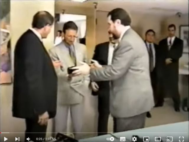
Interview with Jack Durban (Marks' associate) (Part 1)
Jack Durban / Steven Marks interview TPU (Part 2)
Interview with Steven Marks
Wesley Translate's Akula video #13: Akula's TPU part 2
back to linkpage
suggestion
read and sign my guestbook