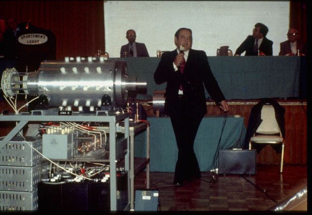
Edward V. GRAY Electro-Magnetic Association (EMA) Motor //(Pulsed Capacitance
Discharge Engine)
Richard Hackenberger - Energy Management Systems
Earl M. Phinney - Pulse generating Apparatus
gray_timeline.odt
| Coils in Series: |
Voltage: |
Resistance: |
Current: |
Inductance: |
| One Coil: |
29 Volt |
34 Ohm |
0.9 Ampere |
23.5 milliHenry |
| Two Coils: |
29 Volt |
67 Ohm |
0.5 Ampere |
73.7 milliHenry |
| Three Coils: |
29 Volt |
100 ohm |
0.35 Ampere |
118.7 milliHenry |
The power source was the Voltcraft Laboratory Power Supply
PS-302A with built-in voltage and current meter.
Resistance was measured with
Sinometer M-830B
Inductance was measured with Voltcraft LCR-9063.
A
ferrite magnet 10 mm in diameter and 4 mm thick was placed at the end of the
electromagnet.
29 volts and a maximum of 0.9 amps were connected to the
electromagnet and the ferrite magnet was fired many times. It reached different
distances each time. But in principle, it reached the same distance regardless of the
number of coils in series. An observation made was that the ferrite magnet reached
longer distances when a spark occurred due to the high current at the connection and
shorter distances when a spark did not occur at the connection.
| Capacitor: |
Voltage: |
Stored Charge: |
Stored Energy: |
| 10,000 uF: |
10 Volt |
0.1 Coulombs |
0.5 Joules |
| 4,700 uF: |
20 volt |
0.094 Coulombs |
0.94 Joules |
| 2,200 uF: |
20 Volt |
0.044 Coulombs |
0.44 Joules |
Capacitor Energy Calculator
The capacitors were fired through an MR 854 (400 volts 3
amperes) diode. How far the ferrite magnet came from the electromagnet was checked
several times. Notably, 4,700 microfarads discharged at 20 volts fired the ferrite
magnet longer than 10,000 microfarads discharged at 10 volts, even though the
capacitor charge was identical. But the amount of energy was double by 4,700
microfarads, compared to 10,000 microfarads. Most notably, however, 2,200 microfarads
discharged at 20 volts fired the ferrite magnet longer than 10,000 microfarads
discharged at 10 volts, even though the capacitor charge was half for 2,200
microfarads than for 10,000 microfarads. But the amount of energy was the same.
I also found that there was a difference between discharging from a power
supply and discharging from capacitors. When I discharged capacitors through a diode,
it mattered more how much resistance and inductance the coils had, than when the
discharge through a power supply that could deliver constant voltage and constant
current. A capacitor discharging through a diode can never supply constant voltage and
constant current.
Conclusion: It was
Nikola Tesla who claimed that the discharge of a charged capacitor was comparable
to the explosion of dynamite. That's probably why Edwin V. Gray wanted his motor to be
powered by high voltage capacitor discharge. The higher the voltage the better. But
3000 volts DC was probably chosen because of the rated voltage of various components.
Hi everyone,
I have experimented today and made a great discovery
that has to do with the Edwin V. Gray capacitor discharge motor.
Take two 4700
uF / 25 volt capacitors. Connect them in parallel so that you get 9400 uF / 25 volts
and charge them with 9 volts from a 9 volt battery. Take an electromagnet whose one
end attracts a permanent magnet. Connect a 3 amp diode in series with the capacitor
and connect the diode and capacitor to the electromagnet. Check how far the permanent
magnet fires.
Connect 2 4700 uF / 25 volt capacitors in series so that you get
2350 uF / 50 volts and charge them with two 9 volt batteries in series, so the total
voltage is 18 volts. Take an electromagnet whose one end attracts a permanent magnet.
Connect a 3 amp diode in series with the capacitor and connect the diode and capacitor
to the electromagnet. Check how far the permanent magnet fires.
By entering the
values in the following capacitor energy calculator:
https://www.omnicalculator.com/physics/capacitor-energy
You get the current
charge and the energy charge and can calculate how far the permanent magnet is fired.
Is that in line with the theory?
You will find more information on my Edwin V.
Gray page that I have made today:
http://gratisenergi.se/gray.htm
- Hermes Atar Trismegistus
Hi Hermes,
I'm not seeing
anything out of the ordinary here. Bear in mind that when you put two equal capacitors
in parallel the total capacitance is doubled, and when you put them in series it's
halved. Also note that when you apply a voltage to a coil the current rises linearly
from zero if the inductance remains constant, and if the inductance varies (as it
will if that coil is pulling in a permanent magnet) then the rate of rise of current
becomes non-linear. Putting a diode in series will also make the current rise
non-linear because the voltage drop over the diode depends on the current.
Thus
the maximum pull here (and I'm assuming you've got springs on the magnet so that you
can see the maximum pull even if you're not actually measuring it except by distance)
will be different based on the capacitance and initial voltage, even when the energy
in the capacitor remains (roughly) constant. If you went far enough to measure the
mechanical energy you're getting out from that magnet movement (by making it do some
work) you'll also find that the work you're getting out is less than the energy you're
putting in. This isn't going to be an easy calculation, though, since the spring force
is not constant. You'll need to calibrate the spring force at various positions of the
magnet, maybe by using a spring-balance, so you know the mechanical force that spring
produces at various magnet positions. Hopefully it will be pretty linear and so that
will make the calculations a bit easier.
Meantime, given the number of people
who have tried to replicate Gray's motor, and failed to find any OU, I think that Gray
himself never actually succeeded, either. Just an error of measurement. Missed
something he shouldn't have done.
Note that you can use
LTspice (or other simulators) to simulate what's happening with your capacitor
discharge through an electromagnet, and find the peak current and thus peak pull. You
can thus get a plot of current versus time pretty easily without needing an
oscilloscope and careful measurements.
At the moment I'm also getting emails
from Henk, who remains convinced that he can use 3-phase power and a diode-bank to
transform voltage higher whilst not reducing current, and can then use the HVDC he
gets to drive an inverter and get more energy out than he put in. Basically he thinks
VARs can be converted to real watts, since he's not considering the phase shift of
voltage versus current on the AC side. He's relying on a DVM that tells him the RMS
voltage and the RMS current, but doesn't measure phase. Doesn't seem to matter how
many times I tell him that the phase is important in AC measurements.
Some
things just aren't going to give you OU. Magnets and electromagnets driven by a
relatively low rate of change of current are in that category. Low rate of change is
anything slower than around a nanosecond at the sizes of kit you're using. You're thus
several orders of magnitude too slow to even have a chance of seeing any deviations
from expected results, and even then you'd need some very high fields (thus large
voltages and current) which can only really be achieved using resonance. That's why
the EMDrive uses a high-Q resonator and 2.45GHz, and even then the anomalous force
produced is only of the order of millinewtons.
See
http://physicsfromtheedge.blogspot.com/2021/02/horizon-engineers.html
for another way to get an anomalous force. Note that this violates Conservation of
Momentum, and thus also has the capability to violate Conservation of Enrergy. All the
other "space drive" ideas (at least the ones that actually work) also have those
capabilities. This is also something you can test for yourself fairly easily.
The big problem here is that nearly all of the "traditional" Free Energy devices
didn't actually work. There's really not a lot of point in replicating them - lots of
other people have tried and have failed to get a positive result, even when they've
done all the right things. That doesn't mean that making energy is impossible, just
that the methods they attempted didn't work, and that in order to succeed you need to
do something different. The value of the lists of failed Free Energy inventions is in
telling you what you shouldn't be doing if you want to succeed. One of those things is
obviously connecting capacitors and coils, and discharging capacitors through them. No
chance of success.
Best regards, Simon
Hi Warren
I am not
sure but think the results of Hermes two experiments; one is the caps in parallel,
(for double the UF capacitance but same voltage) the other with them with in series,
(for double the voltage but half the UF capacitance) will show that the
double-the-voltage series capacitors will fling that magnet much further, and by a
factor in power much more than X2....so results of experiment is high voltage in caps
"much better"
This because the voltage in a cap is a function of being SQUARED
and its not "linear" (Actually its a function of the voltage-drop during discharge and
the voltages are measured being squared in the formula (voltage before discharge
squared minus the voltage after discharge squared) See the formula I will post at
bottom of this, I have put it up alot...its not that complicated even I can understand
it!
So thats why I think Hermes was saying he found out something important
relating to the GRAY motor as the GRAY motor is very very high voltage motor up around
3000V maybe, and it was always recovering the flyback/backemf too. which is up in the
60K voltage region too.
You know where you can use those caps is the Ismael Aviso/Dmitiri 2000VDC cap
discharge that flings up a shorted-out flat or donut shaped coil up around 35ft Look
in FILES section here for the Dmitri/Ismael "repelling force" experiments in a folder
there...Its not that hard to do basically parallel alot of mosfets for the switching
and wind a couple coils, stand back and dont get killed by the 2000V...Ismael got it
to work off a 9V battery, and two 1.5 batteries in series for 12V, then he could blast
it 14 times (more than that actually) to 35 feet, 20 second recharge time between
blasts, and batteries only dropped about a volt thats alot of power for very little
input...Dmitri replicated it, has the circuits to copy etc.
Farad value of cap / ii2
X
(Voltage in cap before discharge SQUARED
MINUS
The voltage in cap after discharge SQUARED)
X
Number of discharge events per
second
= Watts
So if 10,000uf cap, and the voltage sinks from 100 to 50v during
discharge and you do it just once per second that is:
,01 / 2 = .005
100 squared
=10,000
50 squared =2,500
10,000 - 2,500 =7,500
So;
.005 x 7,500 x 1 =
37.5 watts
Do it 10 times a revolution and its 370.5 watts.....
Monkey with the
numbers, like doubling cap UF or doubling the voltage drop see what is important for
more power released...
Kone
Hello Kone and thanks for the links and
explanation. I think it is the voltage that drives the current through the
electromagnet. 9 volts and 34 ohms provide 0.26 amps. While 18 volts and 34 ohms
provide 0.53 amps. This means that for the same electromagnet with X number of turns,
the double current causes the
magnetomotive force to double.
I have redone the experiment and fired the
permanent magnet straight into the air. The result was that the permanent magnet
reached higher up in the air when I fired the electromagnet at 18 volts / 2350 uF than
when I fired 9 volts / 9400 uF.
I think another reason why Edwin V. Gray used
DC discharge capacitors was because a coil's reactance is zero at DC. While the
reactance of a coil increases with frequency. But that's just a guess and I may be
wrong.
Best Wishes, Hermes
Hi Hermes
The capacitors stores
the same amount of energy when having same capacitance and same voltage across them.
The difference is how they discharge that energy (i.e. doing work). When in series the
capacitance is low which gives less capacitive reactance which again makes them
discharge faster. As power (P) is the ratio of work (W) to time (t)
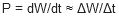 the power is
greater when the discharge happens fast even though the energy is the same.
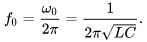
Discharging a capacitor with capacitance C into an inductor with inductance L makes
them oscillate at the LC
resonant
frequency
the power is
greater when the discharge happens fast even though the energy is the same.
Discharging a capacitor with capacitance C into an inductor with inductance L makes
them oscillate at the LC
resonant
frequency
 The
diode limits this to a half oscillation (half period). To have most power (shortest
discharge time or highest frequency) requires the product of L and C to be small. Thus
minimizing the capacitance requires greater tension (voltage) to store the same amount
of energy. A too fast discharge may vaporize or explode the coil or demagnetize or
reverse magnetize the magnet. A shorted copper ring (or disc) would do instead of the
magnet as a short will reflect the magnetic field (Lenz' Law). The ring or shorted
coil has to have low resistance and inductance.
The
diode limits this to a half oscillation (half period). To have most power (shortest
discharge time or highest frequency) requires the product of L and C to be small. Thus
minimizing the capacitance requires greater tension (voltage) to store the same amount
of energy. A too fast discharge may vaporize or explode the coil or demagnetize or
reverse magnetize the magnet. A shorted copper ring (or disc) would do instead of the
magnet as a short will reflect the magnetic field (Lenz' Law). The ring or shorted
coil has to have low resistance and inductance.
Physics Demo -- Jumping
Ring:
https://www.youtube.com/watch?v=Pl7KyVIJ1iE (1:40). This is DC or AC and not a
single capacitor discharge.
High Powered Electromagnetic Disk Launcher:
https://www.youtube.com/watch?v=0BjBaRynFGQ (1:20). Outside launching.
2kV washer launcher high speed capacitor bank explosion:
https://www.youtube.com/watch?v=whxiWKoj_mE (1:01). This one goes really high.
Regards
Ole
Hi folks,
I came across this page that Hermes
kindly put together:
http://gratisenergi.se/gray.htm which
describes a scenario about charging capacitors to different voltages and getting more
energy out. I've also spent the past year or so reading everything I can about E.V.
Gray and Don Smith amongst others. I'm now connecting the dots and seeing a lot of
similarities between their approaches. I think it all boils down to capacitors.
Charge of a capacitor is Q = CV Energy stored in a capacitor is E = 0.5 x CV˛
Here is a table of some examples:
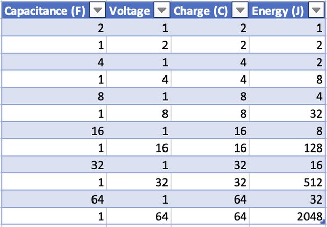
For the same charge it is very advantageous to have a lower capacitance and
higher voltage as it results in much more energy.
@Hermes - did you follow this
any further? It seems like something of considerable interest.
There is also
the two capacitor paradox
to consider. Take a 100V 100uF capacitor and connect it in series to another empty
100uF capacitor. The energy on the 100V capacitor is 0.5J. The two capacitors then
equalize voltage so they have 50V each.
The energy on both capacitors is now
0.125J each, giving a total of 0.25J. Where did the extra 0.25J go? If it's possible
for the energy to simply disappear, then conversely it must be possible for energy to
appear.
Best regards,
Lee
Hi Lee,
I believe that the
Edwin V. Gray free energy engine worked with a combination of at least three parts.
1) The lifting force of an electromagnet depends on the iron core and ampere
turns. With the same iron core, the lifting force will be the same if a current of 2
amperes flows through 1 turn as if 1 ampere flows through 2 turns. My experiment with
1 and 2 and 3 coils connected in series showed that the permanent magnet landed at the
same distance no matter how many coils I connected in series. The only difference was
that with 1 coil the current was 0.9 ampere. With 2 coils connected in series the
current was 0.5 ampere and with 3 coils connected in serie the current was 0.35
ampere.
http://gratisenergi.se/gray.htm
2) the use of pulsating high voltage DC voltage to drive enough ampere through the
electromagnet which was wound with many turns and therefore had large DC resistance.
Your discovery that it is better to have high voltage and small capacitor instead of
low voltage and large capacitor, can be valuable. An advantage of a small capacitor
compared to a large capacitor is that the small capacitor has a faster charging and
the discharging time, which is suitable for working electric motors with high
revolutions.
3) the use of ionizing spark gap that release electrons that
increase the current through the electromagnet.
http://gratisenergi.se/sparkgap.htm
Best Wishes, Hermes
Hi Hermes,
Thanks for providing more
details about your experiments with capacitors and coils.
The equations I'm
looking at are:
t=RC (capacitor time constant)
Q=CV (charge)
E=(CV^2)/2
(energy)
From t=RC, we can see that a low R and low C equals a low time
constant. Therefore it's much quicker to charge a small capacitance through a low
resistance.
From E=(CV^2)/2, we can see that a high voltage yields much more
energy due to the squaring of voltage.
Now, voltage isn't part of the time
constant equation, so that means we can charge the same capacitance to varying
voltages and the elapsed time will be the same.
From what I've read, it seems
that voltage simply gives electrons a higher energy. In other words, voltage doesn't
affect the number of electrons that are used to charge a capacitor.
My theory
is that it should be possible to charge a capacitor to an extremely high voltage using
a low current, and the energy produced when discharging said capacitor will exceed the
input power.
It's probably a silly endeavour, but like I said earlier, I have a
gut feeling about this one. I will of course publish my results regardless of how it
turns out. I don't mind admitting failure.
I've performed a preliminary test
where I hooked up a TV flyback transformer to a ZVS which is powered by a DC/DC
converter connected to two 12V 7Ah lead acid batteries. The DC/DC converter is set to
output 22V. I had a 0.01uF film capacitor inbetween the flyback positive and negative,
with the negative wire not directly connected but set about 1cm away from the pin. I
then had a spark gap inbetween the capacitor leads, at a distance of 2cm.
The
sparks were very loud indeed and gave me quite a fright when I turned it on. The
sparks looked like a white ball about 5cm in diameter. The energy in the spark looked
like much more than the power being consumed by the ZVS. I recorded that the DC/DC
converter was pulling 5A at 22V = 110W. I've seen sparks from a 12kV NST and they
seemed feeble in comparison. Obviously empirical evidence is required, so I'm going to
work on that next and record input/output.
Best regards, Lee
Hi
Sven,
I've done a fair amount of research into semiconductor switches and there
doesn't appear to be anything that's able to switch voltages over 3.3kV at decent
amperage. For example, I'd like to dump a high voltage capacitor into a coil in a
short time period, but when you calculate the instantaneous current it can amount to
hundreds if not thousands of amps. I had a look at SCRs, but while they can handle the
amps there is a complexity in triggering them and the rise times aren't comparable to
SiC MOSFETs.
For now the humble spark gap seems to be the best and simplest
approach for high voltage & high current applications. It does bring a set of new
problems like electrode erosion, Ozone production etc. Maybe a vacuum tube (Thyratron)
would be better and safer. Once a working voltage & amperage is arrived at then I
guess it would be a good point to consider semiconductors.
Best regards,
Lee
Hi Hermes,
As I said earlier, you can use
LTspice to simulate this sort of stuff. You probably need to be a little careful
on the maximum timesteps, and to disable the waveform compression (.opt plotwinsize=0)
so that you can see the fine details, but otherwise you're just dealing with switching
capacitors around, with preferably some parasitic resistances and inductances so the
components aren't too idealised.
So yep, there's an oddity that when you charge
the caps in parallel, and then switch them to being in series, looks like the stored
energy changes. Since this energy change happens when you simply change the wiring,
and you can use switch contacts rather than semiconductors, looks like you ought to be
able to produce more energy out than in pretty easily.
Bear in mind that the
sum capacitance of the series caps is lower than each cap on its own. Thus if we have
a set of 10 10,000µF caps which can each take 10V, and we charge them in parallel at
10V (so capacitance is 100,000µF) and then change the wiring so they are in series,
you now have 100V across the set that you can drive through a resistor to measure the
energy it delivers. However, the effective capacitance is now only 1000µF at 100V.
You'll notice here that the capacitance is 1/100 of the parallel capacitance when in
series, and the voltage is 10 times higher so the 0.5CV˛ comes out to being exactly
the same in both configurations.
I suggest you actually set up this simulation
and explore it yourself. You'll find that this doesn't allow you to produce or destroy
energy, no matter how you connect them. It was just an illusion in the first place,
because the whole situation wasn't considered.
Enough people have experimented
in this area that, if it worked, we'd have been exploiting it for at least a century.
There's nothing really special about using high voltages here - the same maths works
for whatever voltage, and the sparks and arcs are actually lossy so we try to avoid
them in a good design.
Of course, it's a lot cheaper and safer to do the tests
using LTSpice than wiring up some real caps and putting a few kV on them. If it were
a real effect, then the simulation would show the same effects since again this is
mathematical in nature. As it is, the simulation shows you that there's no point in
trying to produce energy this way, though it might be advantageous if you want a DC-DC
converter either up or down.
Best regards, Simon
back to linkpage
suggestion
read and sign my guestbook