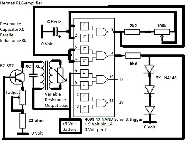
Hermes RLC-amplifier
Resonant Frequency Calculator
Hi Ole and Simon,
"When
resonance occurs in a parallel RLC circuit, a local current circulates between the
inductor and the capacitor. This current can be very high, while the circuit current
as seen from the source can be low."
Now I have made the first schematic of
Hermes RLC-amplifier: It has a squarewave adjustable frequency generator and a
constant current transistor. The transistor will be on when 4 is
high and off when 4 is low. The 2k2 resistor is a
current limiting resistor. The 100k potentiometer adjust the frequency.
C Hertz capacitor alternativly charge and discharge. A big capacitor lower the
frequency, while a small capacitor increase the frequency.
The transistor can
be any small signal transistor with a safe output power of 625 milliwatt. The
22 ohm is a current limiting resistor limiting the transistor emitter
current to 0.75 Volt/22 ohm = 34 milliampere. The potentiometer that is connected
between the 22 ohm resistor and the transistors emitter can be of any
value. The higher value the less collector current. The transistor maximum
output power is 9 Volts*34 milliampere = 300 milliwatt. The primary output between the
collector and +9 volt source can be short circuit without burning the
transistor. Also the secondary of the transformer can be short circuit without burning
the transistor.
I see that Hermes RLC-amplifier can be used for three
things. First find out if there is any larger current circulating between the
capacitor and transformer in the RLC circuit. Second a frequency generator for free
energy studies and third as a tester for suspected malfunctioning transformer.
Best Wishes, Hermes
Hi Simon, Mehmet and Nick,
Simon I have four
questions:
1) How are you in these COVID-19 times?
2) Are you
vaccinated?
In Sweden older people who was full vaccinated early in 2021 is
dying from the delta variant.
3) Why is the revolution green website down? I
got a "Error establishing a database connection" message.
4) Do you think
Hermes RLC-amplifier has any merit? I
haven't built it yet as I want your opinion first.
Best Wishes, Hermes
P.S click on the image to read Resonance in Series and Parallel RLC Circuit...
P.S Mehmet and Nick how are your free energy research doing? Any news?
Hi Hermes,
Limitations here because of Covid don't have a lot of effect on me.
Since I had Covid back in March I don't need to get vaccinated - the immunity from the
disease is longer-lasting and more comprehensive than that from the vaccine. Of
course, the authorities want me to get vaccinated.
Worth getting dome
Ivermectin even if you're vaccinated, since the vaccination won't stop you catching
Delta (or other variants) or being infectious. However, seems Ivermectin is no longer
for sale here.
R-G went down about a week ago, and I haven't had a reply from
Ken from the email telling him that. Probably the end of R-G. Fairly obviously, if Ken
looked at the website he'd see the problem himself. Thus he doesn't look at it, and
isn't looking at emails either. No idea when or if the website will be fixed.
I'm not sure of the reason for your "RLC amplifier". It's basically a signal
generator, and produces a square wave (or fairly close to square wave). Any reason why
you don't just use a standard bench signal generator? That would give you a wider
range of frequencies, a controllable amplitude, and the ability to deliver sine,
triangle, or square waves. There are even digital versions around for not much money
(around the 5-10 euro mark from something like Banggood) that would give you a precise
crystal-controlled frequency. Pretty easy to get a range of frequencies from around
the 1hz to 2MHz too. Benchtop signal generators are a pretty standard thing to have
around (I've got 3 of them).
Best regards, Simon
Hi Hermes
"I see that Hermes RLC-amplifier can be used for three things. First find
out if there is any larger current circulating between the capacitor and transformer
in the RLC circuit."
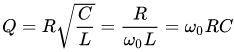
That depends on the quality factor of the RLC circuit.
An ideal LC tank has no resistance and thus can have a high quality factor. When
introducing resistance energy is dissipated. To have the LC-tank store energy by
amplifying the current requires less power loss than the power supplying energy to the
LC-tank. Put in another way that is damping has to be less than one to achieve
oscillations or storing energy in the circuit.
LC circuit:
https://wiki2.org/en/LC_circuit.
RLC circuit:
https://wiki2.org/en/RLC_circuit.
Q factor: https://wiki2.org/en/Q_factor.
Damping: https://wiki2.org/en/Damping.
Regards
Ole
Hi Hermes,
1- I am doing well healthwise.
2- I never took the experimental injection here. ( I read far too many bad
things about it) You may want to listen to this British Funeral home director, he
handles dead people everyday.
UK FUNERAL DIRECTOR EXPOSES WHAT IS REALLY KILLING PEOPLE
Immune system
remedy: Antidote for Spike Proteins & COVID19 Vaccination? Fennel, Star Anise,
Shikimic acid, Pine Tree Needle Turpentine & NANO SOMA
Read more here + video
3- I have no idea why
https://revolution-green.com/ it is
down.
4- I am not qualified to comment on
Hermes RLC-amplifier
5- P.S Mehmet
and Nick how are your free energy research doing? Any news?
I am learning how
to switch on and off permanent magnets not with brutal force, but rather with harmony
with permanent magnets flux lines. Force creates resistance, like pushing a wheel up
heel. Working with harmony, there is some cost involved but there is no resistance.
Therefore output might be greater than input. Think about opposing magnets v/s pulling
each other magnets.
- Mehmet
Hi Mehmet, Simon and Nick,
Mehmet - Thank you for your answers about your free energy research with permanent
magnets. Does you free energy generator have moving parts or is a solid state device
as the Clemente Figueras device? If it is solid state I do think I understand the
working principle despite I have never seen your free energy generator. You can always
learn from people who have made similair research:
https://solidstateelectricgenerator.wordpress.com/a-better-world/
About COVID-19 vaccination in Sweden. Here in Sweden almost every new COVID-19 case is
the delta variant and almost all new cases having COVID-19 on the intensive care units
are unvaccinated people. Vaccinated people on the intensive care unit are rare and
almost all 80 years and older. What does it tell you? Simon and Mehmet, I had a mild
infection of COVID-19 in June, but I have also vaccinated twice since then so I am
full vaccinated. The only side effects of the vaccine was cold sweat and fever for one
day after taking the vaccine. I collect COVID-19 remedies and last time I read about
fenofibrate:
https://www.openaccessgovernment.org/fenofibrate-could-reduce-covid-19-infection-by-70/116973/
If you test positive for COVID-19 you should immediatly call your doctor and
ask for fenofibrate 145 mg. That might save your life. Mehmet I too have a remedy for
COVID-19. You can read it at:
http://gratisenergi.se/corona.htm
Simon - Ole has been most kind to give me the links to
LC circuit:
https://wiki2.org/en/LC_circuit.
RLC circuit:
https://wiki2.org/en/RLC_circuit.
Q factor: https://wiki2.org/en/Q_factor.
Damping: https://wiki2.org/en/Damping.
It was as I suspected. My idea with Hermes RLC-amplifier is to inject a
parallel RLC with a small constant current and then harvest a larger current from the
parallel RLC circuit. But the current amplification in the parallel RLC circuit
depends on the Q factor and Damping:
"For a parallel RLC circuit, the Q factor is the inverse of the series case:
Consider a circuit where R, L and C are all in parallel. The lower
the parallel resistance, the more effect it will have in damping the circuit and thus
the lower the Q. This is useful in filter design to determine the bandwidth. In a
parallel LC circuit where the main loss is the resistance of the inductor, R, in
series with the inductance, L, Q is as in the series circuit. This is a common
circumstance for resonators, where limiting the resistance of the inductor to improve
Q and narrow the bandwidth is the desired result."
Mehmet- Thank you very much
for giving the idea of how to construct a solid state free energy generator. I have
all the parts so it will be easy to construct and Simon, I do have a standard bench
signal generator that is fully digital with analog output so I can test my free energy
idea.
Best Wishes, Hermes.
Hi Hermes,
If you use a
resonant circuit, it stores energy. You feed it a certain amount of energy per cycle,
and the energy builds up until the losses per cycle equal the gains per cycle, at
which point you have stored Q times the energy per cycle in the circuit.
The
voltage you get and the (out of phase) current you get at that resonance are also a
lot higher. Again, the higher the Q of the resonator, the larger the currents,
voltages, fields, etc..
For a short time, this circuit can deliver more energy
than is going in, because it can deliver its stored energy. In the same way, you can
use a flywheel to store mechanical energy, and deliver that energy in a much
higher-power pulse than the energy input.
However, the number of joules of
energy you get out will always be less than you put in, because you lose some of those
joules to heating the wires and components. The system will not be OU, and won't be
able to run itself.
None of these sorts of systems have ever been OU, though of
course many people have claimed it because they are incompetent at the measurements
(or were running a scam). They either cocked up the measurements or lied. If anything
had worked, then we'd be using it by now.
How many times do I need to explain
this before you actually get the point that trying these types of OU design will never
work?
If you want to succeed in OU (and if you don't, then why work at it?)
then you need to do something significantly different to these failing ideas. There
are two ways I can currently see. One is violating 2LoT and converting environmental
heat into usable power. See the Lovell Monotherm. The other is violating CoM, and thus
CoE. See Richard Banduric, Mike McCulloch, the PNN, EMDrive, and a few others. Both of
these methods exploit loopholes in the laws of physics, and involve setting up
conditions that don't naturally occur in order to set up the conditions for breaking
of symmetry. They also require some study, and if you look at my articles on
revolution-green.com you'll find pointers.
Best regards, Simon
@Hermes
I seen you asked the same question about ZVS induction heaters on
energetic forum. No one replied you for a reason, that source you quoted is false.
Loading the circuit dampens the resonance and causes input to increase proportionally.
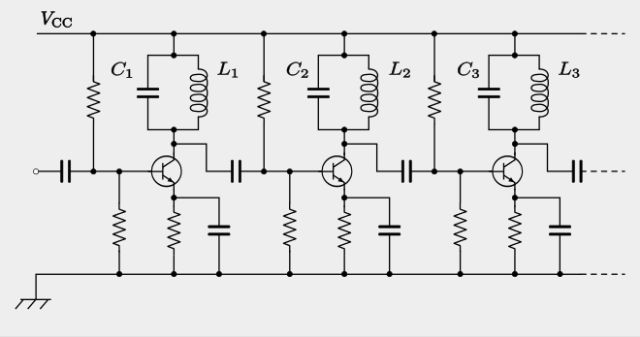
As for your schematic, i am not sure what you imagine to achieve. RLC
amplifiers are an old and common thing, for example below is shown parallel RLC as
part of intermediate frequency radio amplifier, RLC increases the gain at the resonant
frequency because gain of a common emitter stage is proportional to RL/RE.
- nix85
Hi Hermes,
Perhaps you have the wrong thread? See
HERE.
I see no relation to the content of this thread? Please post to your own
thread if this is your work and stay on Topic!
The Mr Preva Experiment
is a lot more involved than just an RLC Circuit!
I can assure you, there is no
Amplification of Electrical Energy in a standard RLC Circuit!
Best Wishes,
Chris
back to linkpage
suggestion
read and sign my guestbook