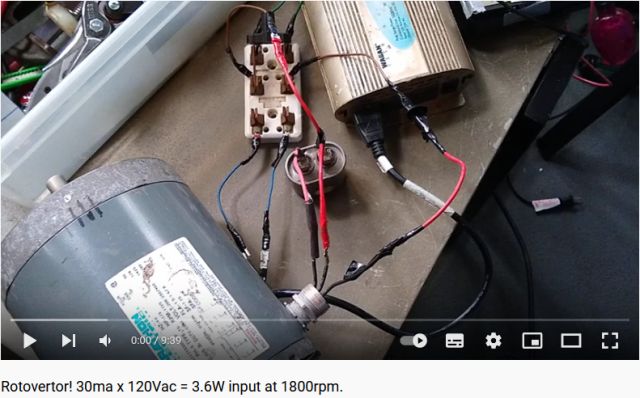
Rotovertor 3ph motor conversion
Blacksand and Aircored AC Flat Disc Rotor Motors on Rotoverto AC Motor shaft
Rotovertor AC Motor with Flat Disc AC Motor on shaft
Rotovertor Motor and Muller Generator on shaft with Rotating Disc invertor
 Rotovertor! 30ma x 120Vac = 3.6W input at 1800rpm
 Rotovertor wants to keep going...
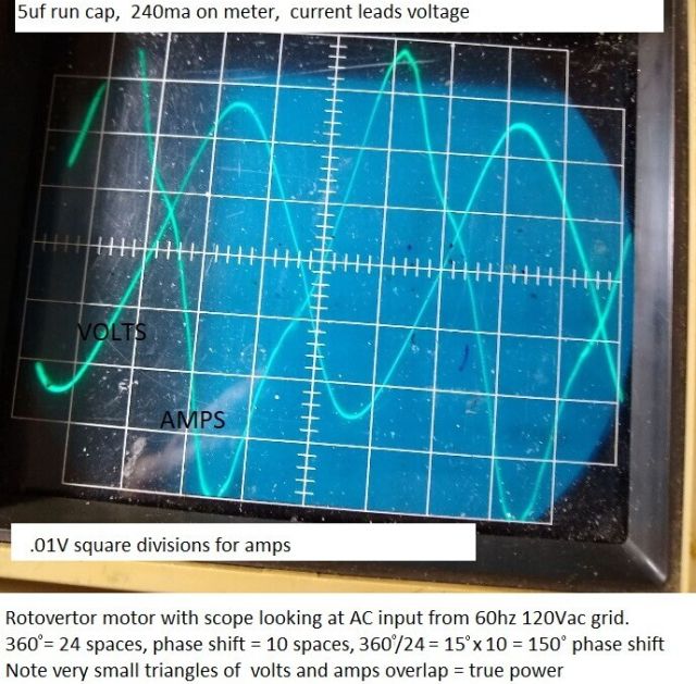
 Rotovertor! 230ma on meter means LESS draw in watts compared to 40ma on meter!
 How scope looks when rotovertor is disconnected from grid and winding down.
 Comparing BiTT transformer in parallel or in series to run cap phase of rotovertor
 Rotovertor makes 42W "back to source" while BiTT creates 14W into resistive load.
 Current running "back to source" from rotovertor motor with BiTT in series to run cap.
 180 degree phase shift of the AC input to rotovertor motor with 5uf run cap.
Hi Warren'
You are going off on the wrong path measuring
amperage with meters only into that big 3ph transformer. You need to scope it as soon
as possible to see phase shift. Because its an inductor, the primary of it, there is a
big phase shift on the input to it, no matter what. And when a phase shift, it is only
the "overlapping in time" voltage and amps that is the REAL POWER being consumed. What
I just saw with the rotovertor input, looking at it with scope, is that the actual
true watts input to the RV is LESS when the meter shows MORE!
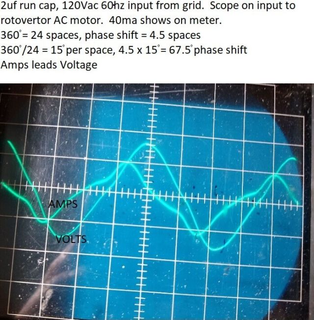
I showed two
scope photos in attachments last post, one is when the meter show only 40ma input x
120V (2uf run cap) The other is when meter shows 240ma input x 120V (6uf run cap)
You would think there should be an increase in watts x 6 when the meter goes up to
240ma. But actually watts input is LESS with the motor using thr 6uf run cap, rather
than the 2uf run cap. LOOK at the small triangles where volts actually overlaps with
amperage in the scope photos. THIS is the real power being consumed. Look at how much
more amps is "circulating" at 240ma, BUT that is not overlapping with the voltage but
for a small smidgen in time! That is the real power being consumed....Meters show the
amperage "flowing" or circulating. But not the percentage of that amperage that makes
for real power.
Hector never taught us about phase angle, power factor, and
actual watts in AC whenever there is a phase shift far as I know and thats not too
far. I will guess because we are stupid monkeys and if you cannot figure it out for
yourself then you dont deserve to know would be Hectors punishment to the monkey
brains.. Taking Hectors "word on it" was not good enough for him. He wants us to
figure it out ourselves. OK so I just did, (with much help from Gerry!) and the meters
are WAY OFF measuring what the actual power input is. They only measure the
circulating current. When Hector says "this is how they hide it" this is exactly what
he means....."They" whoever they are (probably nazis) do not want the "untermunchen"
to go past the stage of measuring watts input to rotovertors, or transformers. with
meters only. In AC, if there is a phase shift between volts and amps in time, the
overlapping period in time of volts and amps is the only real power....very plainly
seen on scope. Look at the two photos, where the monkeys would assume it is six times
more watts consumed at 240ma input as compared to 40ma input, (using meters!) Actually
just looking at the overlapping small "power triangles" using a scope, the 240ma input
is actually twice as less power input than the 40ma input. This plain as day seen by
comparing size of the "power triangles" where volts and amps actually do overlap in
time.....in the rotovertor, this is good x 2, since shaft torque increases when larger
uf run caps are used.
Kone


Hi Simon,
Kone claim that both his BiTT:
http://gratisenergi.se/bitt.htm
and his Rotovertor:
http://gratisenergi.se/rotovertor.htm
is overunity. But only when connected to the line socket. Not with a battery
and inverter. Why?
Best Wishes, Hermes
Hi Hermes,
Instantaneous power input is instantaneous volts times instantaneous amps. Power is
the integral of the instantaneous power over time (preferably 1 second, but whole
number of cycles).
When taking power from the wall-socket, the line impedance
behind that socket (and the other loads on the supply-line) affects the measurements.
You probably won't get a sine-wave, either. Makes phase measurements a bit less
precise.
These things are not overunity. If they were, then you could run it
from a battery and inverter, and charge the battery at the same time as supplying some
load. Thus the measurement of OU on the line power is wrong, since you can't get the
same OU using an inverter.
Look at the waveform here. Does that look like a
good sine wave to you? None of the calculations you normally apply to AC are accurate
if it's not a sine wave in the first place.
Thus just put this one down to
measurement error. Not worth putting a lot of time into it.
If you really want
OU, try the electric thrusters I told you about. After all, if you manage to produce
the thrust, that will in fact work.
Best regards, Simon
back to linkpage
suggestion
read and sign my guestbook


