Free Energy experiments with buck converters
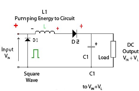
Héctor D. Pérez Torres version of a Buck Converter
Copyright A.R.K. Research
 For free energy some other source of
energy is needed than the one supplying the energy to the input stage. Something like
Pierre Cotnoir is doing or
Tariel Kapanadze
is doing by mixing
different fields
into a single field before harvesting the difference in energy levels would be better.
A parametric change
of the inductance or the
capacitance could be another way
to achieve the goal if it is getting
free energy.
For free energy some other source of
energy is needed than the one supplying the energy to the input stage. Something like
Pierre Cotnoir is doing or
Tariel Kapanadze
is doing by mixing
different fields
into a single field before harvesting the difference in energy levels would be better.
A parametric change
of the inductance or the
capacitance could be another way
to achieve the goal if it is getting
free energy.
Regards
Ole
Hi Hermes,
You may find it useful to read
http://revolution-green.com/theory-perpetual-motion/ and then decide on exactly
how the environmental energy is going to go into your system when it's running. Pretty
well by definition (since you're energising it with AC) it will have a higher
energy-level than the environment, and so energy will leak out of it rather than go in.
That means that the Hubbard coil and variations of it won't produce energy but will
instead lose it.
A
buck converter uses the property of a coil that once it has current flowing in it
that current will tend to continue to flow, with the energy stored in the magnetic
field. The actual amount of energy stored is 0.5LI˛. We use this property of coils to
change the voltage, but it does not gain any energy in the process. If the volts go
higher, you can't draw as much current and vice-versa. With real devices, there is
an energy loss in the transform and with ideal devices there's only 100% transfer of
power and not more. It looks like you're using a version of Spice to simulate this,
and it's possible that you may thus see more power out than in on simulation because
you're not using a small-enough time-step in the simulation or the plots. If you
either fix the simulation by setting the time-step very small (so it takes a very long
time to simulate) or try this with real-world devices on the bench, you'll find that
there is no energy gain but always a loss.
If you've just drawn these circuits by hand without having a simulator, then maybe you
should get LTspiceIV from LTC at
http://www.linear.com/designtools/software/#LTspice and choose the old version for
XP (fully debugged AFAIK) or the new version for Windows 7, 8 and 10. Your choice.
This allows you to design and simulate a circuit for free, and is very good. In some
ways better than the paid-for ones, except that with ISpice you get a lot of libraries
that you probably won't need and a hefty bill too.
Because you haven't given the value of the coil or the frequency of the chopped DC, I
can't answer your questions. The duty-cycle only matters in as much as you want the
coil current to reach a maximum or minimum, and the frequency should be such as to
match your design criteria. Decide what you want to do, then design the circuit to do
it. Resistors lose you power (they heat up and that's lost power) so you put them in
when you have to. Whatever you do, though, the efficiency will be lower than 100%
though it's possible that if you use the wrong kit or method for measurement you may
think you see a gain. Better metering will show the error.
These ways won't get to overunity. That's about it. Read the Perpetual Motion article
and work out how you're going to make your system take in energy from the environment,
and why it will go in rather than out, and how you convert that energy-flow to useful
output. Trying old plans that have been around for years won't get you anywhere, since
a lot of people have tried them before you and found it didn't work.
Best regards, Simon
Buck Converter
Buck–boost converter
Buck Converter Design
Basic Calculation of a Buck Converter's Power Stage
Self Powered AC-DC Step-up Converter for Low Voltage Energy Harvesting
Cuk converter
DC-DC Conversion Without Inductors
Flyback converter
Free Energy experiment with positive negative split buck converters
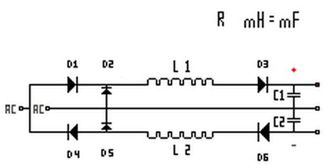
Héctor D. Pérez Torres version of a Positive Negative Potential split
Buck Converter
Copyright A.R.K. Research
D1, D4 are ac split diodes, D2, D5 ARE THE REVERSE SPIKE
BLOCKING DIODES, D3, D6 are the boing back capacitor Inductance self resonance
preventer, as L1 & L2 will tend to resonate each half cycle its energy will be
blocked from going back by D2, D5, and will be passed forward to capacitors C1, C2 by
means of D3,D6.
so within a selected time-frame stream of AC pulse width and
frequency the ac energy can be totally non reflective to source except for the time
and JOULE energy pulse required for the inductors to go into saturation, so this
little "BUTT" plug goes public as is another way to convert RE, RF, into usable power
along the diode plug and non reflective switching ... copy print save all the stuff on
it as i don't want any patenting on it! (H)
Bedini splited the positive,
I splited the negative and the positive.
back to linkpage
suggestion
read and sign my guestbook