Al Hubbard Updates via Philip P.
Some New Hubbard Coil
Articles
"From the Sacramento Union newspaper archive website (google-search
"Sacramento Union Hubbard atmospheric power generator" Transcribed (the originals are
very hard to read)... no photo's or diagrams, just text. Many new details. P.'s
comments are in red.
Sacramento Union, Number 211, Volume 52, December 22,
1919, Page 5 Engineers Wonder as Youth Shows Device He Professes Captures Power of
Universe
Alfred Hubbard of Seattle Demonstrates “Atmospheric Generator”
Without Visible Source of Energy Alfred M. Hubbard, inventor of the machine he calls
the “atmospheric power generator” declares it will revolutionize the world of power
and motion. He says: "It will junk every steam and gas engine in the world ... It will
place electricity in every home without cost for current ... It will advance air,
land and sea transportation hundreds of years ... It will do away with all present
cumbersome methods of electrical production with their generators, transformers and
transmission lines..."
SEATTLE DEC 20 – Has a 19-year-old Seattle boy
solved the problem of the ages and realized the dream of science since electrical
invention had birth? Has Alfred M. Hubbard, son of Mr. and Mrs. William Hubbard tapped
the inexhaustible reservoirs of nature’s energy and harnessed to the use of man the
illimitable power that permeates the universe?
Hubbard has announced the
perfection of an invention he terms an “atmospheric power generator” and made claims
that last night caused Seattle’s leading electrical engineers to doubt the evidences
of their senses and to pause before they condemned as folly the assertions of the
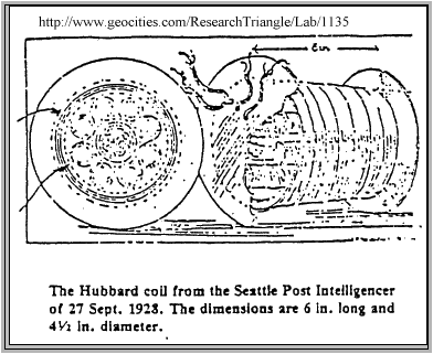
youth. With the apparatus, in appearance a small coil of wire about six inches in
diameter surrounding a permanently magnetic core eight inches long, the entire
contrivance easily carried in a man’s hand. Hubbard gave a demonstration yesterday
afternoon miles from his laboratory that, regardless of the principals involved,
several Seattle engineers declared without parallel in electrical history.
MARVELOUS ANYWAY
An ordinary incandescent electric light connected with
the two terminals of the atmospheric power generator glowed a cherry red for nearly
one hour, and Hubbard volunteered to permit the lamp to burn for as many hours as was
necessary to satisfy the most skeptical.
The young inventor claims that there
are no moving parts connected with his generator; that there are no hidden batteries,
storage or primary; and those who witnessed the demonstration made sure that there was
no outside connection with any source of power.
Hubbard’s explanation of the
phenomenon is that he has succeeded in transforming the earth lines of magnetic force
into electrical energy available for use. While electrical engineers were highly
skeptical last night, and held to the possibility of fraud, as George Quinan,
superintendent of the electrical operations of the Puget Sound Traction Light and
Power company, said “no matter what the lad has done, it is a marvelous
demonstration”. All of the experts agreed that if as Hubbard declares, there are no
moving parts and no concealed batteries, the invention was revolutionary. They had no
explanation to offer for its operation.
J.D. Ross, superintendent of the
municipal lighting department, and one of the foremost authorities on experimental
electricity in the northwest, declared it possible that Hubbard had stumbled upon the
answer to the question of the ages – can the power of the atmosphere be utilized?
ALWAYS POSSIBLE
“It is hard to believe”, said Ross, “that this
boy has done what the world’s scientists have failed to do, yet there is much in the
statement that in the field of electricity nothing is impossible. I am inclined to
believe, since I have not seen the device, that there is some trickery, but those who
have seen it tell me that such is apparently not the case, and I must confess that I
have no alternative but to admit the demonstration is almost unbelievable”.
Carl Edward Magnusson, acting dean of the University of Washington college of
engineering declined to even hazard a guess as to the principal involved in the
device. “It sounds like trickery to me and I can hardly believe that the experiment as
it has been described to me actually took place” he said. “I will not venture an
opinion until I have seen it”.
C.F. Uhden, special engineer of the city, in
charge of the Skagit River power development, declared himself intently interested in
the invention and after canvassing the possibilities of chicanery, admitted that he
wouldn’t dare form an opinion until he has seen the apparatus in operation. “It’s
always possible” he said, “though there have been many to make the claim and no one to
substantiate it in the past”.
DENIES PERPETUAL MOTION
But
Hubbard, because his device has not been patented, owing to complications arising with
his backers, it is said, has refused to allow technical men more than a glimpse at the
apparatus. Hubbard appears untrained in business, and like many inventors, cautious.
He has no appearance of the charlatan and made the blanket statement that any of the
seemingly extravagant claims for his invention he was willing to prove by operation
under test conditions. All that could be learned from Hubbard regarding the
construction of the instrument follows:
BURNS LAMP LONG TIME
Hubbard’s claims for the invention bring into being a host of dreams. If, as he says,
he can obtain four kilowatts, equivalent to more than five horse power, from a
contrivance weighing less than twelve pounds, then his claim that he can build a
generator less than eighteen feet in length to develop 18,000 horse power of
sufficient electrical energy to drive the new battleship New Mexico is not
unreasonable, in the opinion of the engineers.
Hubbard offers to build for $50
a generator large enough to drive an automobile and much smaller than present engines
(it ended up costing $90).
He offers also to build a generator and equip it
with a motor to drive an airplane and to weigh about as much as the present motor
without fuel. The tank and gasoline at present are one of the greatest weight factors
of the airplane. The Hubbard generator, according to its inventor, would give the airplane
unlimited flying range.
Hubbard, who says he has a laboratory at his home with
apparatus valued at $10,000, declares that he worked 18 hours a day for two years
before he came to Seattle and (has continued working) during the year since perfecting
the apparatus. His first model was built a year and a half ago, he said.
Hubbard asserts that his four-kilowatt machine has continuously excited the equivalent
of 120 ordinary 25 watt house lamps to full brilliancy for three months. The device
during this time, (he says he is ready to take an oath on it), did not receive outward
stimulus, and at the time of the test was completed the lights were burning at the
same brilliancy.
The machine, he said, is composed of several layers of wire
about a steel core, which is magnetized after the construction is complete. Once
magnetized, the core needs no further attention, he said, and the entire device will
deliver energy unremittingly for an indefinite length of time. “I place a maximum of
fifty years on the life of the generator” said Hubbard, “simply because one must fix a
maximum. I know no reason why it would not last until time rots the insulation away
from the wires”. Hubbard denies that his device is a perpetual motion machine.
He maintains that it taps the vast storehouses of cosmic energy and the apparatus is
founded upon sound scientific principles. (Which ones are those?)
GOT THE
IDEA FROM A SPARK
“I have hitched my wires to the tail of the universe you
might say”, he said. Hubbard has a high school education. His father is an electrical
engineer, he said, and the family formerly lived in Spokane. It was while he was in
charge of the air compressor at the Hercules mine near Coeur d’Alene, Idaho, that he
first became interested in the problem. “I watched a great belt flit by me day after
day, he related, and I noted thousands before me had that I could draw an electrical
spark from the belt with my finger. I had always been interested in electricity and
had studied a great deal from books since I was a small boy. The spark of the belt
fascinated me. One night I conceived the idea that developed later into the generator.
I will not say that it utilizes in any way the current derived by friction as from the
belt. That is not accurate. I am not prepared to divulge the nature of the actual
translation of energy.
SMALL SIZE PUZZLES
He also said that eight
such lights had been kept burning from electricity furnished by the apparatus while
locked into a safety deposit box for seventy-two hours. This is an unheard-of feat,
according to the men of science. Hubbard was reticent concerning the whole matter,
declining to tell more than a little under pressure and consenting to a demonstration
only after much persuasion. Electrical engineers who were not privileged to witness
the demonstration last night ventured theories at the operation. They said that while
there were theories that the apparatus seemed to coincide with, if Hubbard has what he
says that he has, he has accomplished what most hard-nosed savants have believed
impossible. Most of the engineers inquired as to the possibility of hidden springs
driving a small dynamo, but most of them abandoned this when they learned that
approximately 85V had been delivered by the machine under test conditions for almost
one hour. Other believed that a varying of a powerful magnetic field by a paraffin or
fiber disc might produce this effect but admitted this highly improbable. They doubted
that so great a pressure could be obtained from a contrivance of so small a size.
SACRAMENTO UNION, Volume 212 Number 18, January 18, 1920 Page 4
NEW
AIR MOTOR IS BAFFLING – INVENTION OF SEATTLE YOUTH PROVING MYSTERY TO INVESTIGATORS.
HIDDEN WIRE THEORY IS DISPROVED BY HOISTING MOTOR INTO AIR. SEATTLE, Wash.
– Experiments even more baffling than those witnessed by local electrical experts
recently when Alfred M. Hubbard, 19-year old inventor, demonstrated his atmospheric
power generator, were shown later when the young man threw the switch into place on a
twenty-five horse power electric motor and instantly the motor jumped to life,
developing its full capacity of power. Skeptics present said the motor was connected
by unseen wires. Hubbard hoisted his motor with a block and tackle and allowed those
present to make examinations and tests to assure themselves that no wires extended
from the motor. The result of the demonstration was an even greater mystery regarding
the young man’s discovery, if it is one. Hubbard went even further. He told how the
motor was made to operate, took it apart and showed those present just what it
consisted of. He would not tell, however, how he had arranged the parts to change the
polarity at the rate of 120 times per second, which he says is the secret of his
invention.
ORDINARY MOTOR USED
The motor was an ordinary
alternating current motor of twenty-five horse power, equipped with the usual
armatures and fields. Hubbard’s change on the motor was to insert six rods of
manganese steel wrapped with wire in the head of each of the two armatures and a
change in the wrapping of the two fields. This is the same principal upon which he
says his small model works. In the center of the inserted wrapped rods Hubbard places
a steel core which, when first put in place, is then magnetized. These rods and the
steel core make up the physical construction of the power unit.
Hubbard says
the secret of his discovery lies in the wrapping of the coils. Last July 4th, Hubbard
says he had a boat equipped with a similar twenty-five horse power motor. With this
power it was much faster than a gasoline engine boat. He entered races at Union City
on Hood’s canal. He won by a big margin. His success attracted the attention of many
boat owners who were curious as to the engine that drove his craft. Hubbard told them
freely he says, of his discovery and inventions, knowing the secret could not be read
from an exhibition of the motor. Hubbard says his backers became alarmed at his
free-handed manner of displaying his invention and insisted that he dismantle the
boat.
NEW MODEL PROMISED
Hubbard is loath to give a public
demonstration, as many here want him to do, until he has completed his patents, he
says. He will, however, show his new model on its completion within the next two
weeks. Hubbard’s mail since his announcement of the invention has contained several
bona-fide offers from large corporations in the east now using gasoline motors, to
adopt his device if it proves satisfactory. Hubbard smiles at these letters and
replies courteously and remarks to his friends that the day is not far distant when
the writers will be forced by competition to adopt his device.
Hubbard’s smiles
are not saved alone for enterprising corporation representative’s letters. He smiles
at the experts and university professors when they accuse his of having a battery
somewhere in the device. Hubbard’s mail also contains letters from women, accompanied
by photographs, offering proposals of marriage. Several attorneys have written
offering legal advice. One letter offers the theory that Hubbard’s device is operate
by personal magnetism.
While engineers have not yet given Hubbard’s device
their endorsement, scientific circles here have been aroused to a discussion of
age-old master problems of science. Theories unnumbered are offered to account for the
performance of Hubbard’s device, but Hubbard persists that he has told and shown all
there is to tell and see about. Within the next two months, Hubbard says, he will fit
one of his discoveries to an automobile. He says the device will continue in operation
until shut-off by a switch, or if left running continuously, until the metal it is
composed off disintegrates.
The Post-Intelligencer (Seattle WA), Thursday,
July 29, 1920 ~
Hubbard Coil Runs Boat On Portage Bay Ten Knots An Hour; Auto Test
Next Seattle Boy Inventor Makes Good His Claims of Last December When He Announced
Discovery to P.I.
Hubbard's Claims
If young Hubbard's claims are
correct regarding the newest coil he has perfected, and which propelled a boat
yesterday, these are a few of the things the coil would do without cost other than the
initial outlay of $90:
Drive a large touring car at normal speed.
Illuminate
a moderate-sized office building.
Furnish current for lighting, cooking, and
heating for a large residence.
Heat seven two room apartments.
Alfred M.
Hubbard, Seattle boy inventor of a device which for want of a better name he terms an
atmospheric power generator, yesterday made good his prediction that he would drive a
motorboat with the apparatus as a source of power.
An eighteen foot boat,
propelled by a thirty-five-horse power electric motor, which obtained its current from
the Hubbard coil, was driven about Portage Bay on Lake Union. Among those who
witnessed the demonstration was a well-known local capitalist, the inventor's father,
William H. Hubbard, and a Post Intelligencer reporter.
The boat traveled at a
speed of between eight and ten knots--silently, except for the whirring of a chain
belt which connected the motor with the propeller shaft. When the chain belt was
removed, the motor ran free at a speed estimated at 3,500 revolutions [the rest of
this line is unreadable]
No Hidden Wires Found
To guard against
the possibility of ordinary storage batteries concealed about the boat as a power
source, instead of the Hubbard coil, both electric motor and coil were lifted free
from their blocks, but no hidden wiring was revealed. The coil used as a power unit
was eleven inches in diameter and fourteen inches in length. According to Hubbard,
tests of the coil show a current of 280 amperes and 125 volts, which, he pointed out
was equivalent to approximately forty-five horse power, or sufficient to drive an
automobile. The current is pulsating.
The electric motor was approximately
twelve inches in diameter eighteen inches in length. It had been reconstructed in
order to be used with the Hubbard coil.
After his ride in the strange powered
craft the capitalist declared that he was frankly puzzled, but that he desired an
electrical engineer in his employ to make an examination of the coil before he felt
free to discuss it.
Since last December, when the Post-Intelligencer first made
public the claims of the youthful inventor, he has been more or less in retirement,
perfecting his coil. He took up his residence in Everett where, with the assistance of
Everett backers he worked on his device.
A local capitalist agreed to witness a
demonstration of the coil to determine its practicability as a power source. The
motorboat was fitted with blocks on which to rest the motor and the propeller shaft
geared for a chained belt.
When the motor was first tried out after its
installation in the boat it ran backwards. So involved are the connections between
the motor and the coil that fully a half-hour's experimentation was necessary before
the motor shaft revolved in the right direction.
That the capitalist was
frankly skeptical of the device was plain when he,with two other passengers, boarded
the boat at the Seattle Yacht Club wharf. All the machinery that was visible was the
coil and the motor, the latter plainly geared to the propeller shaft. The boat shoved
off, Hubbard threw the switch, and instantly the boat began to pick up speed.
It circled about the bay and returned to the wharf, with never a slackening of speed.
The wires connecting coil and motor had begun to heat under the excessive current,
and, fearing that some part of the coil might give way under the extra heavy strain
put on it, Hubbard declined to permit the motor to be run continuously for any length
of time. It was tried out later several times, after brief periods which allowed the
wires to cool, and its power apparently showed no diminution. No instruments were used
to test its wattage.
The capitalist admitted that the demonstration intrigued
his interest, but that he would wait for his expert's opinion before discussing it.
Following the demonstration, the young inventor declared that within a few
days he expected to drive an automobile with the coil as a power unit.
The Coil
used yesterday had been built especially for the demonstration, and is nearly twice
the size of the coil Hubbard used in his demonstration last winter. The large coil
cost approximately $90 to construct. The inventor says that so far as he has been able
to learn its life as a power unit is indefinite. He declared that a coil large enough
to drive an airplane would be no more than three times the size of the coil used
yesterday, and that a machine thus equipped could fly around the world without
stopping, so far as the power supply is concerned.
While the device has been
patented, the claims for it are so broad that Hubbard says he does not feel safe in
making public his secret. In general, he says, it is made up of a group of eight
electro-magnets, each with primary and secondary windings of copper wire, which are
arranged around a large steel core. The core likewise has a single winding. A coil
thus constructed, he says, is lifeless until given an initial impulse. This is done by
connecting the ends of its windings for a fraction of a second to an ordinary
[two words unreadable R.L.R.] -ing circuit, he says.
The manner of this
momentary charging, however, constitutes the principal secret of the device, according
to the inventor, who says that while machinists have built a number of coils for him
under his direction, they have been unable to "start" them. In the event the power of
the coil should diminish, it can be rejuvenated in less than a second, Hubbard says.
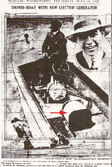
Photo captions (Photos by Walter P. Miller, Post-Intelligencer Staff
Photographer)
1-- Arrangement of Hubbard coil and motor in boat. The motor is
nearest the bow.
2-- Alfred M. Hubbard, inventor of the coil used as a power unit.
3--The boat under way, driven by a motor which obtained its power from the
Hubbard coil.
I have built a Hubbard Coil with 9 ferrite cores. Eight
in serie as input and the central core as output. I used litzwire and the effectivity
was 67% with the frequency of 174,925 KHz. I have decided to give the Hubbard Coil a
second chance, since I have read the patentinformation from
Paul M. Brown
Apparatus for Direct Conversion of Radioactive Decay Energy to Electrical Energy
US Patent 4,835,433 and the
patentapplication of
William N. Barbat
Self-Sustaining Electric-Power Generator Utilizing Electrons of Low Inertial Mass to Magnify Inductive Energy
US Patent Application 2007/0007844.
They are variation of
Alfred M. Hubbard’s Atmospheric Power Generator.

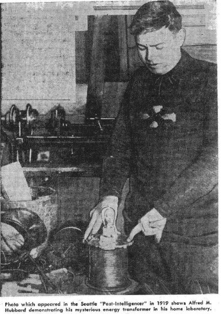
Alfred Hubbard. At Portage Bay on Lake Union,
Seattle, Washington in America, Alfred Hubbard, an acquaintance of Nikola Tesla,
demonstrated in 1919 a self-powered electricity generator design. The generator was
about 14 inches (350 mm) tall and 11 inches (280 mm) in diameter. It powered a 35
H.P. electric motor, which pushed an 18-foot boat which contained no batteries,
continuously around the bay for several hours. This demonstration was witnessed by
thousands and ended because the wiring was beginning to overheat.
It was
said that the cable used contained seven strands of 0.09-inch (2.286 mm) diameter.
Each of those strands would be able to carry 12 amps and so if this is correct, the
cable had a current-carrying capacity of about 84 amps. The diameter of the wire
including the insulation was said to be 0.34 inches (8.5 mm). The inner core was said
to be made of a pipe containing 16 iron rods with 43 turns of wire around it, which if
correct, would suggest 43 turns in 14 inches or 3 turns per inch, implying a
cylindrical coil with the turns side by side, touching each other.
However, a great deal of misleading information, not to mention a good deal of
speculation has been spread around concerning the Hubbard design, which Alfred took
three years to develop. Several years after the demonstration, when Hubbard was
employed by the Radium Company, he said that radium was used in the device, which is
something which I personally, find very hard to believe, and strongly suspect that
Hubbard was persuaded to say that by his employers who were selling radium at that
time.
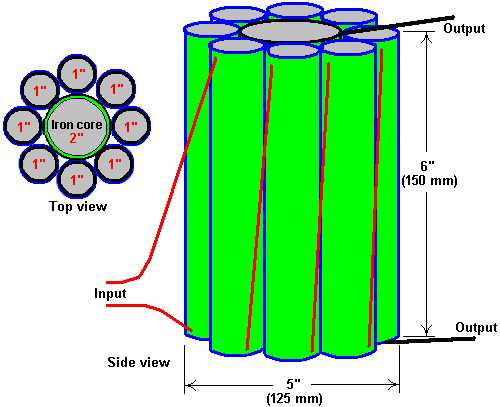
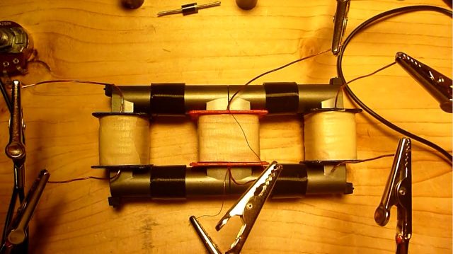
Hubbard made a sketch of one of his smaller generators which was used
for ordinary household electrical appliances and that showed a very simple design
which had eight cylindrical primary coils each of which was wound on a solid iron bar
and connected in series. These primary coils surrounded a slightly larger secondary
coil of some 35 turns wound around a hollow tube filled with metal bars or wires
(presumably of soft iron). This smaller device was about six inches (150 mm) tall
(maximum wire diameter 4 mm including the insulation) and about five inches (125 mm)
in diameter. Each core had only one layer of thick insulated wire and not many turns
were used.
I understand that when a patent was applied for, the patent
application was seized and a spurious “Of National Security Importance” order slapped
on it, acting as an unlawful gag order on Hubbard, prohibiting him from ever
developing, using, showing or selling it or anything akin to it. The US Patent Office
is a privately owned commercial company, and while they will probably be using the
design themselves, they certainly have no intention of ever allowing the public to
have access to it as energy freedom is a major step towards complete freedom.
Consequently, we know next to nothing about Hubbard’s successful design.
The general arrangement might have been something vaguely like this:
Since the suddenly passing of the
free energy legend
John Bedini, Shortly after he introduced the
BEDINI RPX SIDEBAND GENERATOR I have
decided to opensource all my ideas about the
 Hubbard Coil.
As you can see this is the Coutier Coil and the difference from the
Hubbard Coil is that the Coutier Coil has a closed magnetic path on the top and
bottom like an ordinary low frequency transformer with an E and I core. Because
soft iron conducts a
magnetic field 50,000 times more than air. It follows that the effectivity of the
Hubbard Coil can be increased by having squared soft iron rods covering the ends of
the round rods at the top and bottom of the Hubbard Coil.
I think that Alfred Hubbard got the design of his Coil from Nikola Tesla patent of
the rotating field of the
TESLA PATENT 381,968 ELECTRO-MAGNETIC MOTOR.
Alfred Hubbard claimed that the Hubbard Coil worked with atmospheric electricity which
is another name for high voltage. Maybe the round rods had two coils - one low voltage
and one high voltage with a sparkgap to limit the voltage as in the
Kapagen.
Another way to power the Hubbard Coil is to use a
low voltage,
squarewave pulsed,
constant current source,
and connect it to the primary of rod 1. Connect secondary of rod 1 to primary of rod
2. Connect the secondary of rod 2 to primary of rod 3 and so on. Then you can connect
the secondary of rod 8 to the primary of another Hubbard Coil.
In Joseph Cater’s book “The Awesome Life Force”
he attempts to explain the theory of its operation, but it must be clearly understood
that what Cater says is just speculation on his part as Hubbard’s actual design was
never disclosed publicly.
What Cater says is certainly plausible, and even if it is not Hubbard’s design, it is
worth investigating and experimenting with. The mechanism put forward by Cater is
based on the well-known and widely accepted graph of the magnetisation of soft iron
versus applied levels of magnetic force. This graph is highly non-linear and the
central section of the graph rises steeply, indicating that there is a considerable
increase in the magnetisation of the iron for relatively little increase in energy
input.
Cater stresses that the input waveform should be pulsating DC. The method of applying
pulsing DC is then, almost the same as for the Clemente Figuera design shown in
chapter 3, with an offset base level of DC current flow which needs to be maintained
at all times.
Here is the magnetisation graph for soft iron:
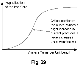
Fig. 29 shows a graph of the magnetisation of an iron core plotted against ampere
turns per unit length. The term “ampere turns” is the number of turns of the coil per
unit length of the coil multiplied by the number of amps of current flowing through
the coil.
The steep section of the curve appears to start at around 3.5 Tesla, and so, a
constant DC current in the magnetising (Hubbard primary) coil needs to provide that
level of magnetisation at all times, and the applied pulsing DC half-sinewave waveform
applied on top of that and since the induced EMF in a coil is directly proportional
to the rate of change of magnetic flux, it follows that the higher the frequency of
this sine wave supply, the better. Using a ramp waveform might well be more effective.
Normal working transformers have ampere-turns which are well below this critical
point. The additional EMF induced in the coils by the magnetisation of the iron
offsets the natural inductive impedance of the coils. This is why transformers have
such a high degree of efficiency. If any material other than iron or special steel
were used for the core, the efficiency would drop significantly. Hubbard used part of
the output power to provide the input power, and so he only needed to provide input
power for less than a second to get the device running. The power supply might well be
of this nature:
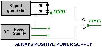
Here, instead of letting the high frequency rectified sine wave (or ramp generator
signal) reach zero volts, and additional DC current supply is maintained, and while
the signal generator pulses add to the overall voltage applied to the device, the
voltage is never allowed to reach zero.
There is possibly another factor which could contribute to the success of the Hubbard
device. At that time, the only insulated wire available had thick and heavy
insulation. This means that adjacent turns of wire in the coil were separated by a
distance equal to twice the thickness of the insulation. Consequently, the gap
resulted in a cancellation of magnetic effects produced by electrons flowing in the
wire. Since inertia is dependent on the ability to generate a magnetic field, the
inertial properties of the electrons would be almost nullified.
There is an optimum distance between the wires which would produce the maximum effect.
It seems likely that the thick insulation on Hubbard’s wire produced this optimum
distance. Most of the resultant magnetic field was that which encircled both wires and
that would be the weaker part of the field. This means that a relatively low EMF could
accelerate a larger number of electrons to a high velocity during a very short period
of time. As the electrons leave the coil, inertia returns. This would result in a
backup of a high concentration of electrons in the coil. Since electrostatic repulsion
is not affected, electrons would be ejected from the coil at a high velocity despite
their increased inertia. This would produce an output of both high voltage and high
amperage:
Joseph Caters Version of the Hubbard Generator.
Although containing conflicting information, there is what appears to be an
implementation of the Hubbard coil system, or perhaps a very closely related device
from Joseph H. Cater. As usual, information on it is limited and not particularly
clear, so the following is just my attempt to piece together some information from
different sources. Much of this information comes from a document which has Geoff
Egel’s name on it and although it seems likely that Geoff is quoting some other
source, my thanks goes to him for sharing what we have here. The diagrams give the
names of various minor websites none of which exist any longer and so these have been
removed as they have no useful purpose any longer. Here is an original diagram from
this information:
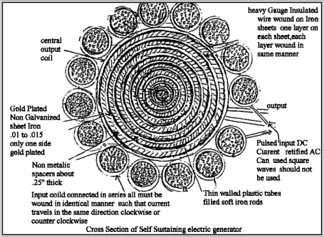
As it seems to me that there are many conflicting details in this information, I am
presenting it here in pretty much the same form in which it reached me. You will
notice that the composite central coil is now presented as the secondary rather than
the primary. It should be stressed that Hubbard never disclosed his design publicly
and so this, and similar information elsewhere, has to be considered to be guesswork.
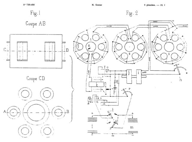
The Self-powered Generator of André Coutier.
Some twelve years after Hubbard’s public demonstration, on 12th January 1933, André
Coutier was awarded patent
FR739458 which is entitled
Self-generating Electrical Generator. This design is so similar to the Hubbard device
that it seems very likely that it IS the Hubbard device under a different name.
Description
The apparatus is composed of a closed magnetic circuit (Fig.1)
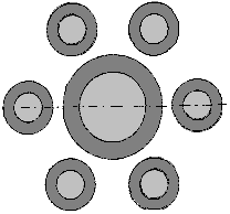
consisting of one soft iron central core coil, surrounded by a number of smaller
diameter soft-iron cored coils. While the diagram shows six coils, that is not a fixed
number. The smaller diameter coils have the same number of wire turns wound around
them and so each of those small coils produces the same current as that which flows in
the coil wound around the large inner coil. The cross-sectional core areas of the
satellite coils is set to be the same as the cross-sectional area of the central coil
core.
The overall design is very simple as shown here:
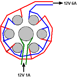
According to the patent, each of the surrounding coils has an output current equal to
that of the central coil. So, if a current of say, 1 amp, is fed to the central coil,
then each of the six surrounding coils will have an output current of 1 amp. As the
six output coils are wired in parallel, the output current should be 6 amps, giving a
COP value of 6 or if you prefer, an electrical efficiency of 600%.
No system is 100% efficient as there are some losses from the wire resistance, the
heating of the wire, eddy currents flowing sideways in the iron cores, etc. in each
coil. So, the overall efficiency will be less than 600% but the overall energy gain
will still be substantial. The voltage remains essentially unchanged but please
remember that as the current increases, so must the wire diameter in order to carry
that increased current.
Coutier uses three of these coil sets as part of his arrangement and he then takes off
a controlled amount from the output to provide the needed input for the system:
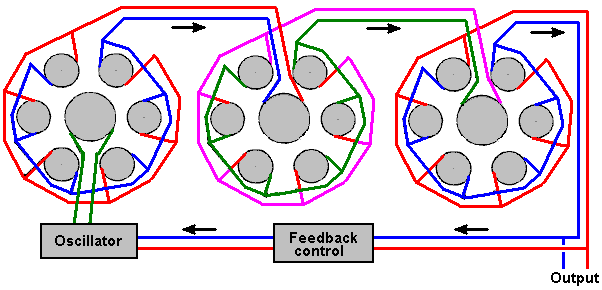
The output is alternating current. Coutier chooses to use an isolating transformer in
his feedback control which feeds the necessary input current to his oscillator
circuit. He also uses a mechanical vibrator as his oscillator as way back in 1933
there were no readily available semiconductors. His overall circuit diagram uses
infinity symbols to indicate Alternating Current and it looks like this:
An attempted translation of the patent text is:
The device consists of a closed magnetic circuit (fig. 1) consisting of one central
core of soft iron, in the shape of a cylinder. There are N similar satellite cores,
set parallel to the central core and placed in a circle around the central core.
The central core is an inductive coil with the number of turns required to achieve
saturation of the magnetic circuit with the chosen inductive current. Each of the
satellites coils has the same number of turns as there are in the central core coil.
Given the particular provision of the magnetic circuit, each of the satellite coils is
an isolated transformer and so the current induced in each of the satellite windings
has the same power as the central coil current. Thus, the unit produces a
multiplication of electrical energy. As the output energy exceeds the initial input
energy, we see immediately the opportunity to use some of the output energy to provide
the necessary input energy on a continuous basis.
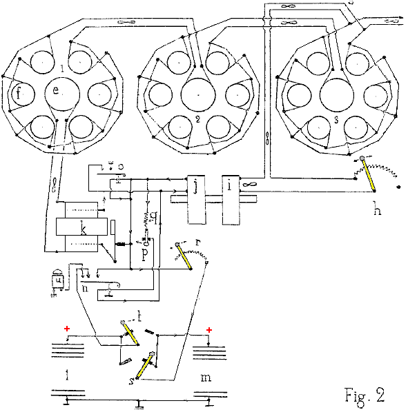
The device used for the industrial model of the perpetual self-powered electricity
generator, established for use in industry, maritime and river navigation, and
traction on railways, is shown schematically in Fig.2.
Three multiplier devices (there can be any number of these devices) are combined in
series, so that the core e of one circuit is powered by electricity from the combined
satellite circuits f, of the previous device. The satellite coils of set 1 feed the
central coil of set 2. Similarly, the set 2 satellite circuits feed the central coil
of set 3.
Each unit with 6 satellites (there can be any number of satellites) determine the
factor of power amplification of each set, and in this case it is 6. With the three
coil sets shown, the power amplification is 6 x 6 x 6 = 216 times the input power.
It is easy, using an output power tap and the rheostat h, to provide the energy
required as the input current. The coil i is magnetically linked to coil j, as they
are mounted on the same core and they form a 1-to-1 ratio transformer. The output of
coil j is used to operate a buzzer k whose AC coil output is used to feed the central
coil e of the first power multiplier circuit.
The device also includes two batteries l and m - which are intended to deal with any
eventuality. One battery can be charged while the other is available for use if there
is an accidental stop of the generator.
Claims
Multiplication of electrical energy carried out by induction of satellite windings,
grouped in a circle around an inductive central winding. The sum of the
cross-sectional areas of the satellite cores is equal to the cross-sectional area of
the central core. Self-generating perpetual electrical energy is achieved by taking
energy from the last multiplier and using it to provide the input current.
This video claim it shows the bi-toroidal topology transformer, but in reality it show
The André Coutier Transformer
with one input coil in the middle and two satellite coils, to the left and right.
Since the suddenly passing of the free energy legend
John Bedini, Shortly after he introduced the
BEDINI RPX SIDEBAND GENERATOR I have
decided to opensource all my ideas about the Coutier Coil. As you know the area of the
center coil of the Coutier Coil is equal to the sum of the areas of the satellite
coils. My idea is to do the opposite, making the center coil area, half of any
satellite coils. The primary will act as an activation coil only and the energy in the
Coutier coil will bounce between the satellite coils like the
Thane C Heins
bi-toroidal topology transformer.
back to linkpage
suggestion
read and sign my guestbook