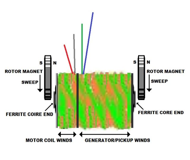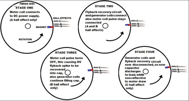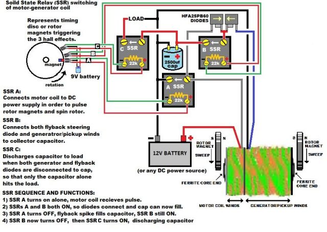
What happens in attachment drawing is through 3 hall effects,
triggered by timing disc on shaft of motor/generator, large caps are filled up non
reflective to motor draw (no lenz) and also the caps discharge to load non-reflective.
The trick is to pre-charge the capacitor with the backemf/recoil/flyback spike
from the motor coil pulse...this is a much faster event than the induced by rotor
magnet filling of the same cap by the rotor magnets, so the flyback spike gets to cap
first and gives it a good boost up in voltage and joules storage...so now the
generator/pickup coils wound on same core, but positioned behind the motor coils,
begin their task of filling up capacitor too, the cap being precharged quite a bit
makes it very easy for generator/pickup coils to continue filling the cap even higher,
and there is no lenz law braking of rotor as there would be if cap after being
discharged sits at zero or a low voltage...but cap sits at around 12 to 15V from the
backspike pre-filling it, so generator coils have it easy.
Finally cap
discharges to load while it is totally isolated, all by itself, connected to nothing
but the load, so this final cap discharge to load makes it impossible to reflect back
onto the motor draw, and the cap discharge is no-lenz, as well as the next sequence of
firing the motor coil pulse, collecting the flyback spike into cap, and filling cap
even more from the generator/pickup winds wound behind the the motor coil, sharing the
same ferrite core....note also this is a dual rotor magnet design, with rotor magnets
reacting to each end of the core.
Kone

Doug
Super nice drawing!
That is clear, and simple, with such a drawing, even I might be able to make one.
Actually my coils in the Muller, are just like that, except without the two rotating
discs of magnets, and importantly, without the ferrite cores.
I did buy the
cores from Russia, quite cheap, but they are slightly too thick to fit my 36 coils I
have already made. I did a test with turning down the ceramic ferrite, using a
diamond tile cutting disc. It works just fine doing it in the drill press, but would
be even better in a metal lathe.
I wound my coils on little pvc tubes made from
electrical conduit, that I put screw thread on one end. By rotating the coil inward,
or outward, I can get micrometer adjustment of the gap between each coil, and the
rotor magnets. Having a ferrite rod that can be removable for each coil, means they
can be either motor, or generator coils, according to needs.
You are so right,
to move me out of the Kromery geometry nightmare, into the Muller. Wiring is a piece
of cake, with the Muller, as there is loads of room to work on it, and no brushes.
Keep up your terrific work Doug. I love your cap dump system, and have to learn more
about making it. Norman seems to be interested in such a Lenz free technique as well.
Cheers Warren

Hi Hermes,
On this, the battery will run down. It's
just a complex way of pushing energy around a system with small losses on each
transmission.
View kinetic energy as a scalar quantity of energy with a vector
of momentum. When we "use" energy to do something, that momentum vector gets
randomised, and we measure this as producing heat. The more you pass energy around,
the more of it will become randomised. The energy hasn't gone way, but because the
directions are random you can't move something with it and do work. Work is force
times distance, and the distance is in a certain direction and so is a vector. Work is
a vector effectively.
We don't need Free Energy. There's energy all around us,
but the momentum vectors are random. The task is to de-randomise those vectors, and
then you have energy you can do work with.
Kone would tell you if he succeeded.
No need to ask me....
best regards, Simon
back to linkpage
suggestion
read and sign my guestbook
 Kone Free Energy Motor Generator


