Overunity in transformer flyback mode
 Flyback converter
DC to DC Power Supply including an
Energy Transferring Snubber Circuit - Bond US 4,899,270
Why is maximum flux attained in transformer when off load?
Why in transformer flux remains constant no load to full load?
Why transformer is called constant flux machine?
Flyback Combined with Induced Generator Coils into Cap and Load
Joel Lagace
Master Ivo
Most or all here (hopefully) understand how transformer works,
primary magnetizes the core, if secondary is unloaded this magnetizing current is
small and almost 90° out of phase with voltage, those few degrees offset from 90° are
due to losses which are circa 1-5% of full load power. Of course when secondary is
loaded it generates the counter flux due to lenz which demagnetizes the core and thus
inductance of the primary suddenly drops and consequently inductive reactance across
the primary which makes current in the primary to skyrocket 'trying' to get the flux
back to previous value which it never fully manages so no load flux is maximum and
full load flux is slightly lower. This skyrocketing of current in the primary due
to lenz of the secondary is expressed as Ia=Ve-Eb/Zs Ia is of course current in the
primary, Ve source voltage, Eb voltage across the inductance of the primary and Zs
impedance aka complex resistance.
This was just a little recap on working of a
transformer, conventional stuff. Now, with that out of the way, consider this...some
food for thought.
Let's establish the facts we can all agree on, if someone
disagrees, feel free to say it.
So called magnetizing current is tiny compared
to load current.
Circa 1-5% of full load power is enough to establish max flux
in the core.
Point is energy stored in the core is proportional to flux.
(Also power transferred through a transformer is flux times frequency but
that's not the point now)
In other words, 1-5% of full load power input
creates full potential energy in the core.
It is quite obvious form this
that every transformer operated in flyback mode should be OU.
But practice
shows it's usually not as simple as that. It is important to understand exactly why.
Let make it absolutely clear to remove any doubt that
1) Flux in the
core is is max in no load state
2) Max flux at same frequency means max
potential energy
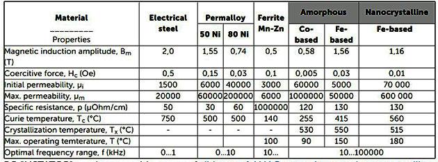
BackEMF is often claimed to be source of OU.
Also,
with high perm cores even smaller current (and power) is needed to generate large flux
so those cores operated in flyback mode should be many many times OU and, of course,
they can be tamed that way, but it's usually not as simple
This should be
cleared up. If someone sees a flaw in my logic, i'd like to hear, but i don't see any.
There is absolutely no doubt that max flux in the core at same frequency means
max potential energy.
And this max potential energy is generated with 1-5% of
full load power.
Why then, if we magnetize the core and then turn off the
source and use the collapsing field to run the load, should not that collapsing field
energy be what it is, a full-load energy.
Nix
TRANSFORMER
EXPLAINED
When transformer is unloaded (secondary open) only magnetizing
current flows through the primary which is tiny compared to load current and is always
(almost) 90° outta phase with the driving voltage, almost but not 90° due to various
losses, namely, eddy currents, hysteresis, magnetostriction and copper losses
(P = I˛R). Average flux in the core is maximum in no-load state and slightly smaller
in the full-load state.
When secondary is loaded, counterflux developed by the
secondary demagnetizes the core and this makes the voltage across the primary to drop
since this voltage is directly proportional to rate of change of flux, we all know
Faraday's (or should i say Henry's) law V=--N*dF/dt.
Voltage across an inductor
can also be expressed as V = L(di/dt)
And current through an inductor
I = (V-E)/Z where V is voltage of the source driving the primary and E is voltage drop
across primary's inductance. Clearly, when secondary demagnetizes the core and flux
through the primary drops, so does it's inductive reactance Z and voltage across it E,
V remaining the same means current must rise and so it does trying to bring the flux
back to the original value but it never fully manages to do so, so, as said before,
max load flux is slightly less than no load flux.
To the circuit driving the
primary, it appears as if a resistor appears in parallel with the inductance of the
primary, bigger the load smaller the resistor appears, obviously.
As said above
magnetizing current is always almost 90° out of phase with the driving voltage while
the load current is always in-phase. At least when the load is purely resistive.
If load is inductive then picture is not so clear, but extending what happens
with the resistive load, we can assume this inductive load will also appear as an
inductor and resistor in parallel and larger the work done larger the virtual resistor
in parallel will appear again bringing IV in phase.
I guess we can extend the
last paragraph to capacitive loads too, of course, electric field just like magnetic
field can also be used to do work and as you all probably know there are various
electrostatic motors, some newer ones of significant power (some even speculate about
replacing magnetic ones).
As for flyback, the only difference is, as said
before in the thread, induction in the secondary happens with a delay (due to internal
diodes blocking the current in one direction) when the primary flux collapses.
Ignition coil uses the same principle, store, collapse, get 10x (or more) voltage in
the primary and x turns ratio in the secondary.
Nix
Hi Simon,
Do you find anything wrong with Nix's reasoning?
Best Wishes, Hermes
Hi Hermes,
Basically, the back emf isn't a source for OU. The
system puts energy into the magnetic field, then takes it out again (with a few losses
from resistance and core losses). From a system point of view, it's symmetrical. Your
energy is either in current times voltage or in magnetic field. Change the number of
turns around that magnetic field, and you change the voltage and current, but not
their product.
Still, the main proof is practical. Test it, and you'll find no
actual extra energy coming out. If there was, this would have been found a long time
ago and we'd be using it for at least a century by now. Of course, with sparks and
other high-frequency spikes, your meter may mis-read it and you might think there's
more energy coming out, but if you're really wanting to be sure you'd put the output
through a resistor and heat some water with it.
If you put a voltage across a
coil, then the current increases at a certain rate. The longer you leave the voltage
on there, the more the current gets and the larger the magnetic field is. With a
perfect voltage source and no resistance in the coil, there's no limit to the current
it will take. A 1-henry coil and a 1V source will take an extra amp every second. With
a real coil and source, you've got resistances so it will asymptote to a limiting
current and probably release the magic smoke that makes it work. If you've got a core
in the coil, then that will have a limiting magnetisation, above which the inductance
of the coil goes down and the current rises faster. Still, apart from the losses, the
energy you put in goes into the magnetic field anyway. You don't get more energy out
of that magnetic field than you put into it.
It's maybe a bummer, but coils and
magnets working at fairly low frequencies just isn't going to deliver OU. There's no
breaking of symmetry, and to get OU you have to break a symmetry.
One other
thing that might be interesting is that the energy isn't stored in the core, but in
the gap. Doesn't take much energy to magnetise some ferrite, but the gap does take a
lot. Thus to store a lot of energy, you increase the gap size. This also makes the
core less permeable. Still, you may have wondered why flyback transformers always
have a gapped core. Now you know.
There is however a possibility of OU if you
can re-route magnetic flux using less energy than you can get out of the local
flux-change. That's a difficult symmetry to break, but may be possible using the
Meissner effect. Might also be possible using the effect of mechanical stress on
permeability, but I need to test that experimentally. Didn't appear to work using a
quick and dirty test, but maybe a more-complex double path could work. I don't hold
out a lot of hope for the mechanical modulation of permeability, but probably
worthwhile testing even if only to knock it on the head.
To find a way of
getting OU,think of some plan or technique, then reduce it to the underlying
principle. Then look at what people have done before that uses that same principle.
Most of the time, you'll find that a lot of people have thought of the same principle,
maybe used a different setup to test it, and it wasn't OU. Unless you're doing
something significantly different (and can point to that difference and why it is
really different), and you've found what they missed, yours won't work, either.
That's the value of the lists of OU inventions - you know that they don't work
because if they had they'd be in use by now, so there's no point in replicating them.
They tell what not to do. So many other people will have tried them, with variations,
to be certain they don't actually work. It might seem harsh, but you have to find
something that someone else hasn't tried in order to have any chance of succeeding.
Best regards, Simon
Hi Hermes,
Yeah, that’s the
guy. I did not watch all his
videos but I noticed some
of the guys here also gave some comments on his videos. If people don’t have so many
views, usually they respond and do so with sensible replies. Thanks for the page for
the backspike material!
My gut feeling is we need some batteries, some
electronics for pulsing and of course some measuringequipment. But all that is not
enough; you also need communicate with each other. Thats what makes 1 and 1 add up to
more like 3.
Kr Hans
Battery Life Extander and Method -
Fairbanks US 11,133,746
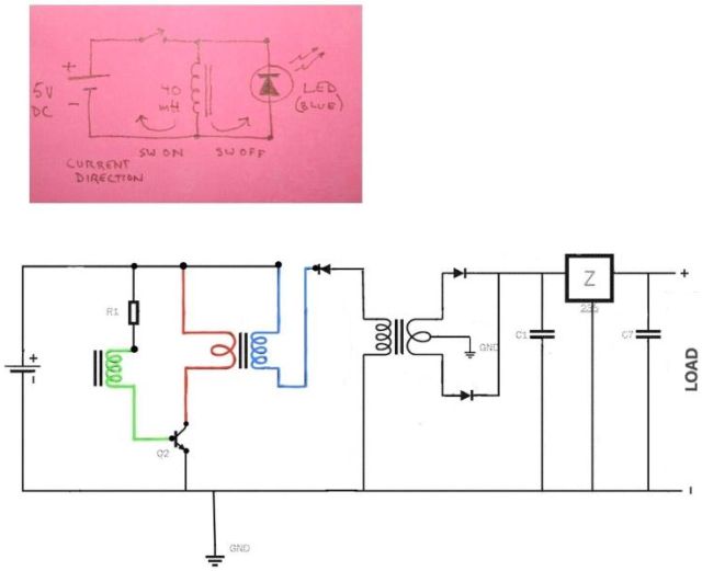
Warren,
It's a patented circuit, not mine. The image above is the
complete circuit minus the various numbers in the patent. I added color to it and
removed numbers to better see the circuit for my own understanding; I figure things
out by redrawing them, etc.
The inventor even has a company that I linked to in
the first post. That's the unique thing about that inventor is that he didn't hide
anything in his patent like so many others do. Amazing to me that he just put it out
there for the world, and the patent office didn't even know what they were patenting.
There's 2 versions that he has in the patent and the one I show above is the
simplest version. It's a brilliant circuit! The Joule-thief sized version that's in
his patent and in the video's is just a proof of concept. If you look at his company
web site, it can be scaled up to run vehicles, helicopters, homes, etc.
In His
old deleted posts on youtube he used to call it an electron accelerator because that's
what it does. It uses the collapsing field of the Joule thief to cause a 350V spike to
be generated in the HV secondary winding.
One side of the HV winding is connect
to the pos of the battery and the other side of the HV winding is connected to an
isolation transformer through a fast diode. The other side of the isolation
transformer is connected to the neg of the battery. Because of the diode direction,
when the joule thief field collapses, the neg of the battery has a positive potential
on it and the positive of the battery has a negative potential on it.
This
causes the electrons in the positive side of the battery to be pulled out of the
positive side of the battery just like when you actually charge a battery (an electron
pump), and sent back to the negative of the battery through the primary of the
isolation transformer. In one of the posts above, he had said his proof of concept was
using a small wall wart transformer with a 120V 120mA primary.
So he raises the
voltage about 3 times which lowers the amp requirements about 3 times. So essentially,
in his proof of concept, he has about a 350V spike with about 50mA worth of electrons
pulled from the positive of the battery being sent through that primary at the rapid
speed of the collapsing magnetic field of the joule thief, which is more than
sufficient for that 120V 120mA primary, and all with a 1.2V rechargeable battery!
What I'm describing to you is my understanding of how it works; I've never
talked with the inventor nor have I ever found any public post by him describing how
it works in detail. But his patent is clear enough to understand it. The circuit
really does work. Of course, he never showed any looping, though, so the battery does
run down. The output is about 5.2V DC at about 850mA, from 1.2V DC at about 1 amp
input. Remember, that's just his proof of concept. For all I know, if you contact him
at his web site,he may just tell you exact details.
Sandman
Warren,
The inventor never showed the details of
his device or gave build instructions, so I can't really say that I replicated HIS
device. I have been playing around with Joule thieves with a High voltage secondary
for many years and I just combined it with a circuit from
rick friedrich's book that is supposedly
based on Bedini's work, and it worked.
If you compare it to the circuit in the
patent, it's almost identical. So not a very thorough search done by the patent
examiner, especially when you consider that Joule thieves predated the patent. The
diode in the image is key in directing the energy flow, much like the led (a diode)
directs the flow in a joule thief. You have to follow electron current throughout the
circuit to really understand how it works to pull electrons from the positive of the
battery back to the negative of the battery and how that all works to give power in
the primary of the transformer. Attached images should help.
Sandman
Hi Simon,
Do you see any broken symmetry in Fairbanks patent?
Best Wishes, Hermes
back to linkpage
suggestion
read and sign my guestbook