17 februari
A very interesting question arose between me and a number of convinced supporters of electromagnetic induction when power lines cut the wires of phase windings in electric generators.
Only one type of generator and similar ones worked on the principle of cutting the conductor by the lines of force - this is the Gramme generator and similar ones Dynamo, where the conductor moved in the gap between the pole of the excitation electromagnet and the core of the anchor, where the winding is wound on top of the metal base of the anchor.
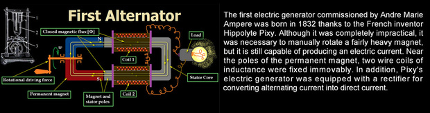
I discussed all this in detail in my publication "The Invention of the Electromagnetic Generator", where I actually stated that the generator of Pixia and the unknown R.M. who wrote a letter to Faraday describing his generator design worked on the principle of changing the Anapol moment, a closed magnetic flux in a closed core.
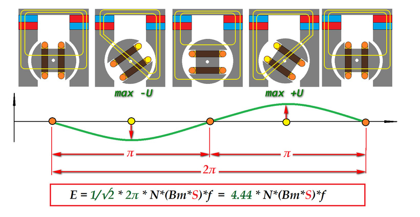
Let's take a quick look at the EMF pulses that can be generated in the Hippolyte Pixia generator design.
Magnetic induction (Bm) is a fundamental characteristic of a magnetic field, like intensity for an electric field. In the SI system, magnetic induction is measured in teslas (T).
The straightness of the conductor (L) of the coil in relation to the magnetic induction vector, in this design will be no more than 45-75* [sin (75° 10′) = 0.9666746. sin (75° 9′) = 0.9666001].
Only a small part of the turns (and only a small part of the turn) can fall into the zone of cutting by the lines of force. Even in this question, it is necessary to understand what kind of induction this phenomenon will cause. Let's consider a real design, and not what is drawn in textbooks.
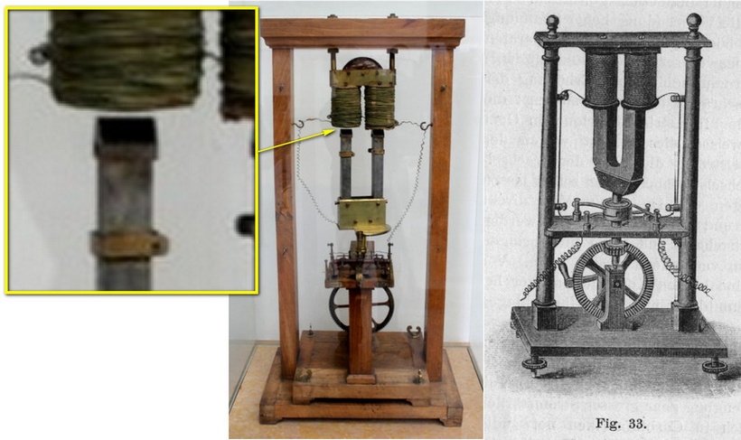
You see, reality is different, especially the shape of the tips, U-shaped magnets. Secondly, the gap between them. Magnetic flux always tends to concentrate towards the lower resistance. So I modeled the approximate magnet ratio (to get closer to reality, I took Alnico magnets.) and made a simulation with the definition of magnetic induction in the area of the supposed conductor cross-section along the lines of force.
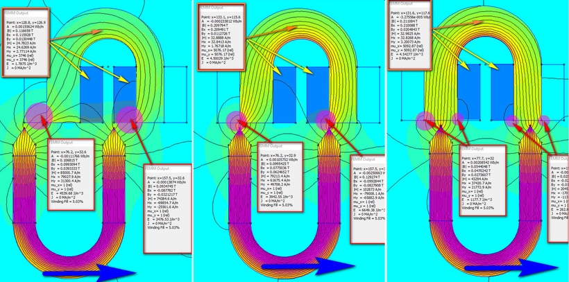
The next step is three simulation episodes, bringing the magnet poles closer to the core volutes with coils. The data is sufficient to make preliminary calculations.
The program calculated the magnetic induction of the coil conductor zone. The best parameter for the first induction option [E = Bm L v] is the first position (left screen), since the magnetic lines cover a larger number of turns with an average magnetic induction value of Bm = 0.1 Tesla. Let's say the core diameter is 30 mm, the circumference will be [P = 2πr = 2π15 = 30π ≈ 94.24776 mm]. Let's take the total number of turns in the coil as N = 200, the number of turns in the cutting zone by magnetic lines will be 10% (200 0.1 = 20), that is, in two coils it will be 40 turns. Further, not the entire length of the turn is active, but only that which is on the straight line cutting the conductor. Let us define it as 40% of the circumference without taking into account the angle [94.2 0.4 = 37.68 mm * 40 dbnrjd = 1507.2 mm (1.5 m).
Next, we need to find out the speed at which the magnetic lines cross the conductor. Let's say a manual drive with a gearbox can spin the magnet up to 500 rpm. The circle around which it rotates will be 70 mm in diameter. We can calculate the angular and linear speeds: w = (1 rpm = π/30 rad/s = 0.104719) 500 rpm = 52.36 rad/s, v = wR = 52.36 rad/s 0.035 m = 1.83 m/s.
Е = Bm L v = 0,1 T 1.5 m 1.83 m/s = 0.27 volts and all two coils in series. And this is the most idealized result. In the second position, the area of the intersected turns will decrease sharply, which will worsen the result even with a slight increase in induction.
We have another result, magnetic induction in the core body. It was Bm = 0.11 Tesla. But this result will act on all turns of the coils, on those sections of the conductor that are in the focus of the closed flow. Anapole moment.
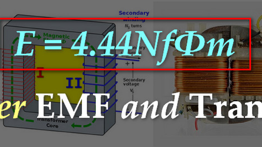
1) Е = 4.44 NBSf (где f = pRPM/60 = 2 500 / 60 = 16-17 Hz; S = 0.025 0.025 = 0.000625 m^2) = 4.44 400 0.11 T 0.000625 m^2 * 16 Hz = 1.95 volt
In the second position we already have a magnetic induction in the core of 0.2 Tesla.:
2) Е = 4.44 NBSf = 4.44 400 0.2 T 0.000625 m^2 16 Hz = 3.5 volt
If we take into account the resistance of all windings and the resistance of the galvanometer, then if only the option of cutting the conductor with magnetic lilies worked, then Ampere would not see anything.
And I will say even more that the principle of the generator of Ippolit Pixia was completely repeated by Kromrey in his generator, which pulled Bedini out of oblivion.
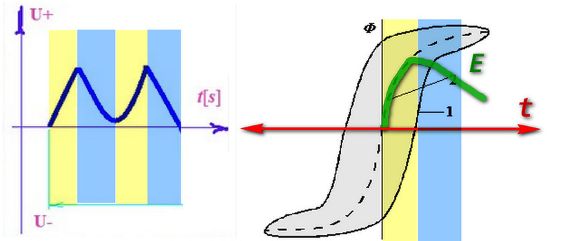
The picture shows an oscillogram of the EMF pulse in the windings of the Kromrey generator.
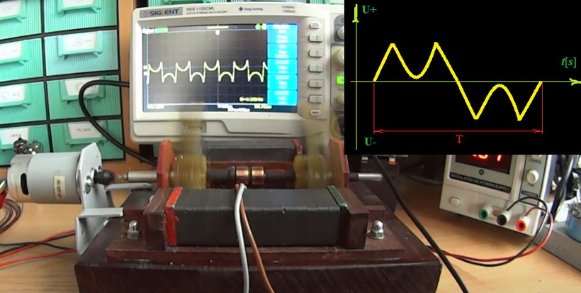
We see dips in the sinusoid peak. This is due to the peculiarities of the hysteresis loop operation when the magnetic flux is closed between the magnetic exciters (permanent magnets installed statically) and the rotating core on which the coils are wound.
The main factor that the transformer formula of EMF does not take into account is the rate of change of magnetic flux. In the core, such a phenomenon as hysteresis has been studied. Let's turn to the definition of the resource Britannica.
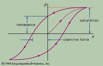
hysteresis, lagging of the magnetization of a ferromagnetic material, such as iron, behind variations of the magnetizing field. When ferromagnetic materials are placed within a coil of wire carrying an electric current, the magnetizing field, or magnetic field strength H, caused by the current forces some or all of the atomic magnets in the material to align with the field. The net effect of this alignment is to increase the total magnetic field, or magnetic flux density B. The aligning process does not occur simultaneously or in step with the magnetizing field but lags behind it.
Let's consider the real hysteresis diagram and part of the EMF oscillogram curve of the Kromrey generator. We see that with increasing saturation, the Magnetic induction indicator changes more slowly, which indicates a change in the rate of change of the flux. In the graph, the primary speed is yellow, the secondary speed of change is blue. The EMF oscillogram with a slow increase in magnetic induction will just give a drop in the EMF nominal value. Which is what we actually observe with our own eyes.
If Pixie or Ampere could obtain an oscillogram of the EMF in their generator, they would have a similar graph, since the third episode of the calculation increased the value of magnetic induction in the core by only 0.01 T (from 0.20 T to 0.21 T).
Electromotive force (Britannica)
Electromotive force, energy per unit electric charge that is imparted by an energy source, such as an electric generator or a battery. Energy is converted from one form to another in the generator or battery as the device does work on the electric charge being transferred within itself. One terminal of the device becomes positively charged, the other becomes negatively charged. The work done on a unit of electric charge, or the energy thereby gained per unit electric charge, is the electromotive force. Electromotive force is the characteristic of any energy source capable of driving electric charge around a circuit. It is abbreviated E in the international metric system but also, popularly, as emf.
Despite its name, electromotive force is not actually a force. It is commonly measured in units of volts, equivalent in the metre–kilogram–second system to one joule per coulomb of electric charge. In the electrostatic units of the centimetre–gram–second system, the unit of electromotive force is the statvolt, or one erg per electrostatic unit of charge.
----------------------------
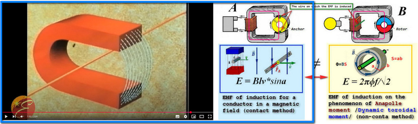
Let's take another great video where the lecturer demonstrates the simplest electromagnetic generator: Simple explanation of a generator - YouTube
The drawing of the educational model can be viewed from Chinese teachers. LINK
The lecturer at the end of his demonstration explains how EMF is induced in a wire, resorting to demonstrating a constant of physics (A) which cannot be applied in this case. In this case, electromagnetic induction (B) works when changing a closed magnetic field (toroidal moment or anapole moment), a Dynamic toroidal dipole.
----------------------------
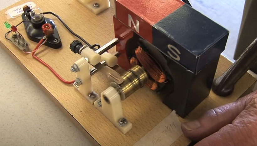
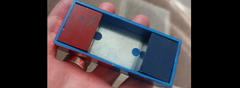
I bought this hand generator for school physics classes. Equipped it with a rotor position detection system based on an Arduino line sensor.
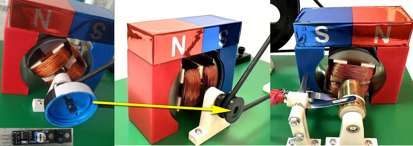
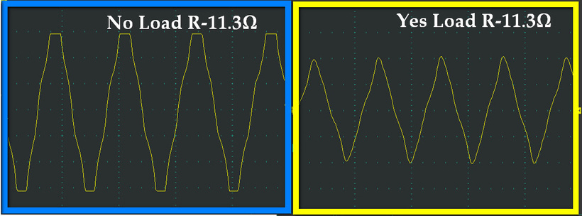
Measured the voltage at the winding terminals in alternating current generator mode with the light bulb on and off. The oscillograms resemble a triangular waveform.
To determine the anchor position, I divided the revolution into two halves, a white and a black line from the center of one pole to the other anchor pole. The sensor, when finding the white line, shows a logical 1 (+), when the black line is logical 0 (-). I connected the oscilloscope probes to the phase output and the generator output and the sensor output. I made the corresponding starts. At first glance, the anchor is turned by wires to the stator pole and the lines should cross the wires to induce EMF. But ... I did the simulation in the FEMM program.
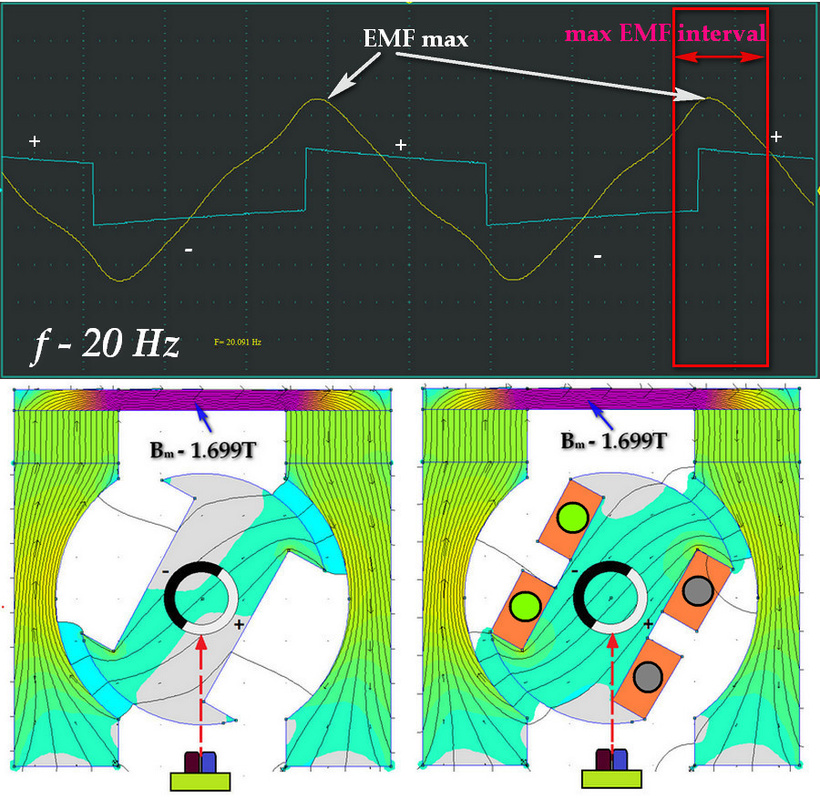
If we look at the graphs, then we can erroneously claim that the maximum EMF is induced at the moment when the magnetic lines cross the conductor. The program in the wire zone shows a magnetic induction value close to zero.

In both maximum positions of the anchor in relation to the stator poles, the magnetic lines cannot physically cross the anchor winding wires.
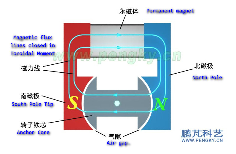
The largest value of magnetic induction is 1.699 Tesla, this is in the iron bridge between magnets with a cross-section of S = 25 mm * 5 mm. In addition, this is the only place where all the lines of force of the magnetic circuit pass. Thus, we can determine the Magnetic flux Ф = Bm S = 1.699 T (0.025 m * 0.005 m) = 0.000212 Veber.
Next, knowing the switching frequency of 20 Hz and the number of turns of the armature coil (500 turns), we can calculate the no-load EMF (without a connected load) based on the transformer formula of EMF:
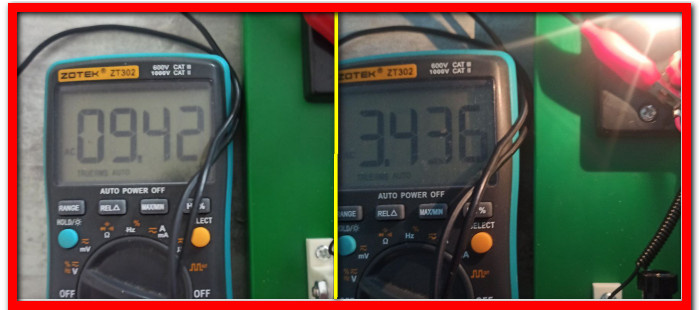
E = 4.44NФf = 4.44 * 500 turns * 0.000212 Veber * 20 Hz = 9,42945 Volt
I myself did not expect such an exact hit, yours may differ by a volt or more, it all depends on the accuracy of the initial data for the calculation. The main thing is shown the principle of how the EMF induction works in systems with closed magnetic circuits.
We can calculate the current on the bulb using Ohm's law I = U/R = 3.4V / 11.3Ohm = 0.30A.
If we apply the general formula for determining the current in a closed circuit, we will not get equality with the measurement of the idle EMF.
I = (E-U)/(R+r) = (9,4V-3,4V)/ (11.3Ω+12,1Ω) = 0,25A
Because the current in the anchor, when the load is closed, contributes to the amplification of the magnetic flux in the circuit (which is visible on the second screen of the FEMM program). Self-excitation occurs, due to which the resulting EMF increases.
We can only calculate this level of the resulting EMF, it will be 11.9 volts.
Let's check: I = (E-U)/(R+r) = (11.9V-3,4V)/ (11.3Ω+12,1Ω) = 0,30A
This is a very important point in the generator design. A good generator is when self-excitation is minimal. In our case, the magnetic system is completely useless, to demonstrate to students that when the anchor rotates in a magnetic field, the light bulb lights up. That's why we get this result.
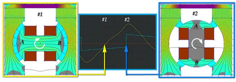
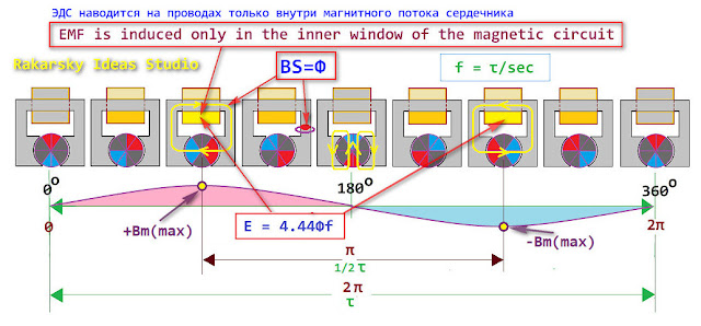
If we consider the components of the magnetic circuit and the EMF diagram, we see that the induction of electromagnetic force occurs when the cross-section in which the magnetic circuit is closed changes. Induction is induced only in the wire that is in the focus of the changing magnetic circuit. At the same time, with a complete closure in the minimum or maximum value, the cross-section in which the magnetic circuit is closed, the induction of EMF is not induced. The main element in this case is the change in the cross-section of the conducting circuit in which there is a closed source of constant magnetic field.
Ф = Bm*S, where S = ab changes
 Modulation with the winding load and no-load showed slightly different indicators of the magnetic circuit of the system.
1) No-load is exactly what we had in mind.
 2) Under load, the armature winding makes a closing with magnetization of the armature and an opening with demagnetization. Which coincides with the EMF graph under load.
But the factor of magnetic lines of force crossing the armature wires is completely absent.
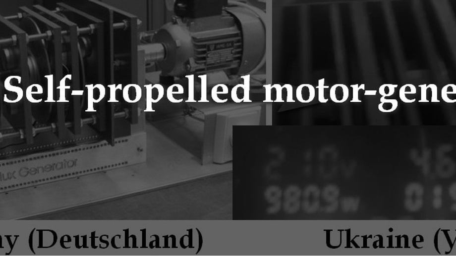
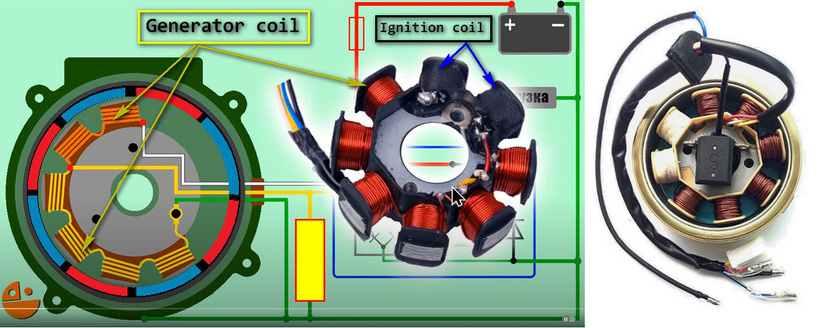
The most obvious proof of the operation of a synchronous electromagnetic generator on the phenomenon of changing the anapole moment is the alternating current generator - installed on the "Scooter". Structurally, eight coils are wound on the stator rods (6 generator and 2 for ignition). Magnetic excitation is carried out by permanent magnets built into the external metal rotating rim. In essence, an improved engineering solution of the first alternating current generator by Hippolyte Pixieu, made by him on the order of Andre-Marie Ampere in 1832.
---------------------------------
For designers of mechanical electromagnetic generators, it is an important factor to organize the linearity of the hysteresis curve, this is achieved by the curvature (unevenness of the gap from the center to the edges) of the pole tip of the magnetic rotor.
Design of synchronous generators (KPI, Kharkov, Ukraine)
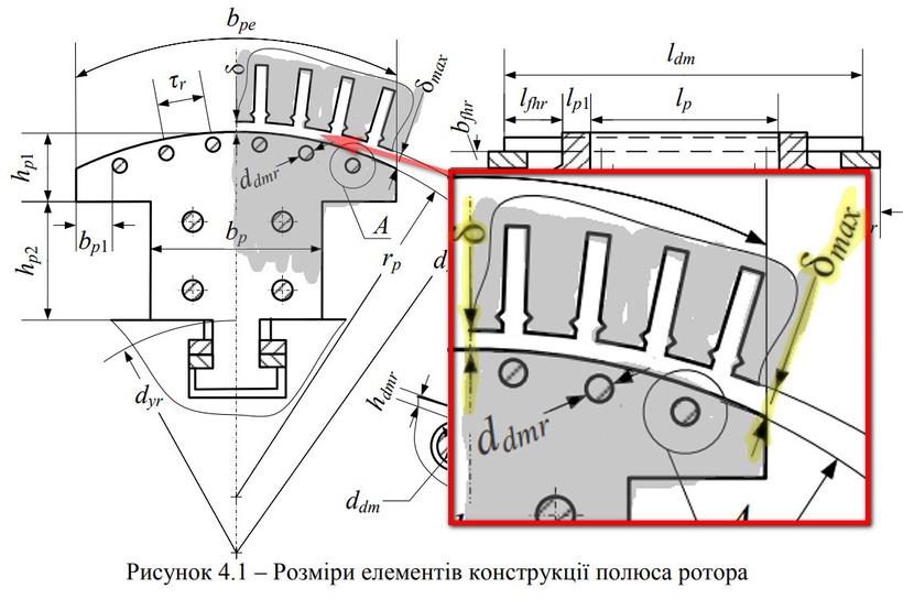
The figure is a screen shot from a lecture at the Kharkov National Technical University of Ukraine. (Figure 4.1 - Dimensions of the rotor pole design elements). Where we see that the gap between the rotor pole and the stator has a curve that increases from the center of the pole tip to its edges: δ - δmax (highlighted in yellow).
Excitation is very important for the operation of the generator, since the excitation current setting controls the final voltage dissipation, and the active power is determined by the turbine rotation speed and its torque. For turbogenerators, the excitation power is approximately 0.5% to 3% of the generator power. That is, it is not difficult to excite the efficiency of generation with overexcitation, the efficiency will be 3333%.
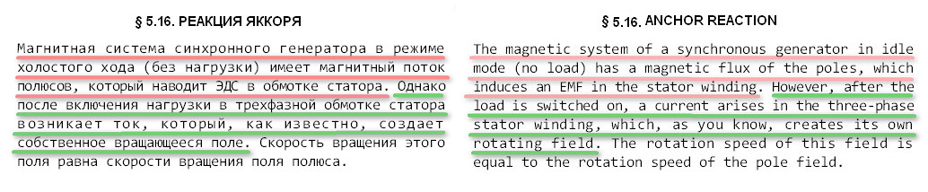
The main task performed by the mechanical force in a mechanical generator is the rotation of the magnetic rotor core with an excited permanent magnetic field (magnetic poles). This magnetic flux of the rotor poles, closing through the stator core with windings, forms a permanent magnetic closed flux ANAPOL, which is characterized by the ANAPOL moment. (American version - Toroidal moment). The physical rotation of these closed magnetic fluxes - toroidal moments, overcoming the magnetic attraction between the rotor and stator cores, is a mechanical cost, not a conversion energy.
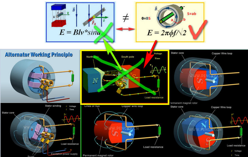
It is enough to explain the alternator operation from the point of view of magnetic field change (toroidal torque) and everything will look differently (highlighted in yellow color obviously does not fit to the generator operation with closed magnetic fluxes).
AC generator working principle
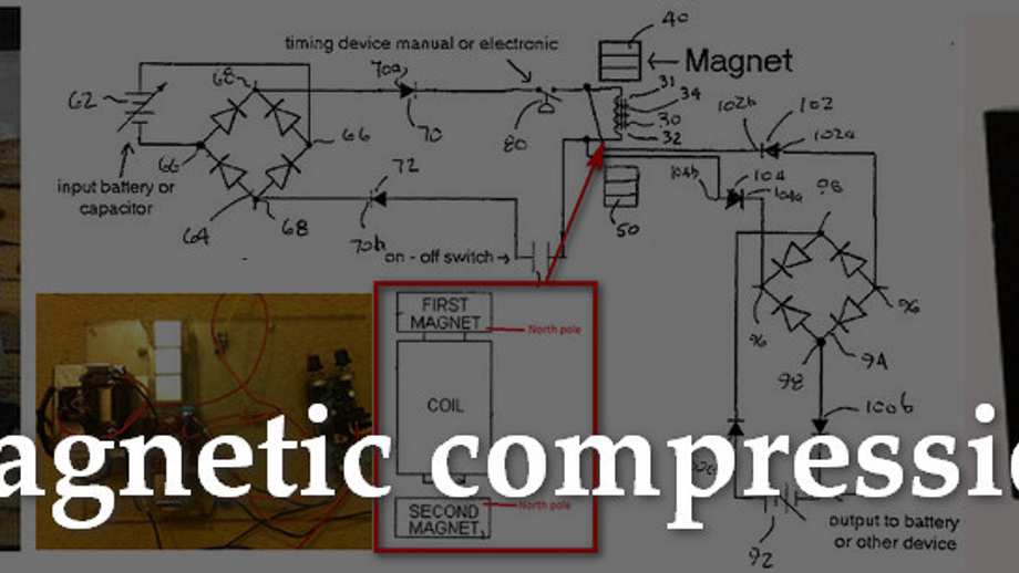
It is only necessary to organize the rotation of toroidal moments in the structure of the synchronous generator, using the algorithm for switching excitation electromagnets. The principle is on the slide below.
Which was actually patented and implemented by Dr. Robert Holcomb. The patent for this type of device and switch was issued by the US Patent Office on 2022-05-17 US11336134B2 (2038-07-01 adapted to the term dii).
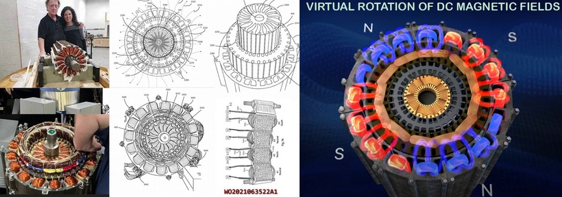
The Hundred Year Mystery - Solid State Electromagnetic Generator
I like that he put all engineers and physicists in trouble with his false standards, which you drool over me. Many people value their dissertations or doctorates, which such a principle of operation simply nullifies. And the education system can also deprive the teaching license if this issue is even raised.
I have researched this issue and proposed the most optimal design of a generator without the physical rotation of the magnetic rotor. The question is only in desire and capabilities. But to get started, just find a suitable armature from a DC motor and a stator with a three-phase winding, make a device for rotating brushes around stationary collector plates with armature fittings inserted into the stator with windings, and see what happens there - anyone with a mind and hands can do it.
Bilder
Skrivande
Videor
Bilder
Skrivande
Videor
.jpg)